Ryobi P3410 Operation Manual - Page 6
Assembly, Features, Operation
 |
View all Ryobi P3410 manuals
Add to My Manuals
Save this manual to your list of manuals |
Page 6 highlights
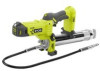
FEATURES PRODUCT SPECIFICATIONS Grease Type Up to NLGI #2 Hose Length 30 in. Maximum Pressure 10,000 PSI Bulk Fill Port 1/8 in. NPT Cartridge Size 13.7 - 14.5 oz. Flow Rate 7.5 oz./min Grease Capacity 16 oz. bulk or 14.5 oz. cartridge ASSEMBLY WARNING: Do not use this product if it is not completely assembled or if any parts appear to be missing or damaged. Use of a product that is not properly and completely assembled or with damaged or missing parts could result in serious personal injury. WARNING: Do not attempt to modify this product or create accessories or attachments not recommended for use with this product. Any such alteration or modification is misuse and could result in a hazardous condition leading to possible serious personal injury. If any parts are damaged or missing, please call 1-800-525-2579 for assistance. OPERATION WARNING: Do not allow familiarity with this product to make you careless. Remember that a careless fraction of a second is sufficient to inflict serious injury. WARNING: Always remove battery pack from the tool when you are assembling parts, making adjustments, cleaning, or when not in use. Removing battery pack will prevent accidental starting that could cause serious personal injury. WARNING: Always wear eye protection with side shields marked to comply with ANSI Z87.1. Failure to do so could result in objects being thrown into your eyes and other possible serious injuries. WARNING: Do not use any attachments or accessories not recommended by the manufacturer of this product. The use of attachments or accessories not recommended can result in serious personal injury. WARNING: Use safety equipment. Protect your eyes, skin, and lungs while handling, loading, dispensing, and removing grease. Failure to do so may result in serious personal injury. APPLICATIONS You may use this product for the purposes listed below: Lubricate grease fittings and other components on vehicles, factory equipment, and other machinery. INSTALLING / REMOVING BATTERY PACK See Figure 1, page 11. To install: Lock the switch trigger by sliding the lock-off button into the locked position. Insert the battery pack into the product as shown. Make sure the latches on each side of the battery pack snap in place and that battery pack is secured in the product before beginning operation. To remove: Lock the switch trigger by sliding the lock-off button into the locked position. Depress the latches to remove the battery pack. For complete charging instructions, see the operator's manuals for your battery pack and charger. 6 - English
-
 1
1 -
 2
2 -
 3
3 -
 4
4 -
 5
5 -
 6
6 -
 7
7 -
 8
8 -
 9
9 -
 10
10 -
 11
11 -
 12
12 -
13
-
14
-
15
-
16
-
17
-
18
-
19
-
20
-
21
-
22
-
23
-
24
-
25
-
26
-
27
-
28
-
29
-
30
-
31
-
32
 |
 |
