Ryobi RTS20 English Manual - Page 18
To Assemble The Sliding Extension, Tables
 |
View all Ryobi RTS20 manuals
Add to My Manuals
Save this manual to your list of manuals |
Page 18 highlights
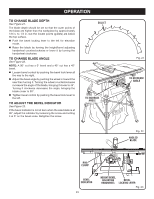
ASSEMBLY TO Check and Align the spreader, Saw Blade, and Blade Guard Assembly See Figure 14. If the blade guard assembly is out of alignment with the saw blade, adjust the alignment of the blade guard assembly. The spreader must be aligned with the saw blade. To check alignment of the spreader: Unplug the saw. Raise the saw blade by turning the height/bevel adjusting handwheel counterclockwise. Lift the anti-kickback pawls and place a framing square or straight edge against both the saw blade and the spreader. The saw blade and spreader are aligned when the framing square contacts both the blade and spreader evenly with no gaps. If the spreader and saw blade are not in alignment, adjustment is needed. To adjust: Unplug the saw then raise the blade guard assembly. Loosen the wing nut holding the blade guard assembly to the mounting bracket. Reposition the blade guard assembly left or right as needed to align the spreader with the saw blade. Once properly aligned, securely retighten the wing nut. to assemble the sliding extension tables See Figures 15 - 16. The rear extension rods are longer than the front extension rods and must be inserted into the plastic brackets under the saw table first. Locate the left sliding extension table and slide the extension rods into the plastic brackets under the saw table. Push the extension table until it rests against the saw table and is completely closed. Position the end plug (LF) over the extension rod (the side with the screw hole and detent facing out) and slide into place. Locate the left indicator. NOTE: the indicators are clearly marked with and "RF" (right) or a "LF" (left). Thread the indicator (LF) into the slot in the front rail. Fit the top slot in the indicator over the detent and the bottom slot over the screw hole. Insert a screw into the bottom slot of the indicator, the hole in the end plug and the extension rod. Finger-tighten. LEFT SLIDING EXTENSION TABLE SCREW 18 SPREADER FRAMING SQUARE RIGHT SLIDING EXTENSION TABLE Fig. 14 EXTENSION ROD END PLUG INDICATOR (lF) Fig. 15
-
 1
1 -
2
-
3
-
4
-
5
-
6
-
7
-
8
-
9
-
10
-
11
-
12
-
 13
13 -
 14
14 -
 15
15 -
 16
16 -
 17
17 -
 18
18 -
 19
19 -
 20
20 -
 21
21 -
 22
22 -
 23
23 -
24
-
25
-
26
-
27
-
28
-
29
-
30
-
31
-
32
-
33
-
34
-
35
-
36
-
37
-
38
-
39
-
40
 |
 |
