Ryobi RTS31 User Manual - Page 34
Making A Bevel Cross Cut, Warning, Making A Bevel Rip Cut
 |
View all Ryobi RTS31 manuals
Add to My Manuals
Save this manual to your list of manuals |
Page 34 highlights
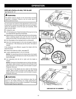
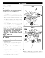
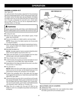
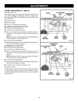
operation making a bevel cross cut See Figures 46 - 47. WARNING: Make sure the blade guard assembly is installed and working properly to avoid possible serious injury. Remove the rip fence. Unlock the bevel locking lever. Adjust the bevel angle to the desired setting. Lock the bevel locking lever. Set the blade to the correct depth for the workpiece. Set the miter fence to 0° and tighten the lock knob. Make sure the wood is clear of the blade before turning on the saw. Turn the saw on. Let the blade build up to full speed before moving the workpiece into the blade. Hold the workpiece firmly with both hands on the miter fence and feed the workpiece into the blade. NOTE: The hand closest to the blade should be placed on the miter fence lock knob and the hand farthest from the blade should be placed on the workpiece. When the cut is made, turn the saw off. Wait for the blade to come to a complete stop before removing the workpiece. making a bevel rip cut See Figure 48. Lock the bevel locking lever. Set the blade to the correct depth for the workpiece. Position the rip fence the desired distance from the blade for the cut and securely lock the handle. Make sure the wood is clear of the blade before turning on the saw. Position the workpiece flat on the table with the edge flush against the rip fence. Let the blade build up to full speed before feeding the workpiece into the blade. Using a push stick and/or push blocks, slowly feed the workpiece toward the blade. Stand slightly to the side of the wood as it contacts the blade to reduce the chance of injury should kickback occur. VIEWED FROM THE FRONT, BELOW THE TABLE SAW HEIGHT/BEVEL ADJUSTING HANDWHEEL TO LOOSEN WARNING: Make sure the blade guard assembly is installed and working properly to avoid serious personal injury. WARNING: The rip fence must be on the right side of the blade to avoid trapping the wood and causing kickback. Placement of the rip fence to the left of the blade will result in kickback and the risk of serious personal injury. Remove the miter fence. Unlock the bevel locking lever. Adjust the bevel angle to the desired setting. BLADE ANGLED TO TIGHTEN BEVEL CROSS CUT Bevel LOCKING LEVER Fig. 46 Miter fence STRAIGHT 34 BEVEL LOCKING LEVER Fig. 47
-
 1
1 -
2
-
3
-
4
-
5
-
6
-
7
-
8
-
9
-
10
-
11
-
12
-
13
-
14
-
15
-
16
-
17
-
18
-
19
-
20
-
21
-
22
-
23
-
24
-
25
-
26
-
27
-
28
-
 29
29 -
 30
30 -
 31
31 -
 32
32 -
 33
33 -
 34
34 -
 35
35 -
 36
36 -
 37
37 -
 38
38 -
 39
39 -
40
-
41
-
42
-
43
-
44
 |
 |
