Ryobi RY10518 Operator's Manual - Page 26
Bar and Chain Combinations
 |
View all Ryobi RY10518 manuals
Add to My Manuals
Save this manual to your list of manuals |
Page 26 highlights
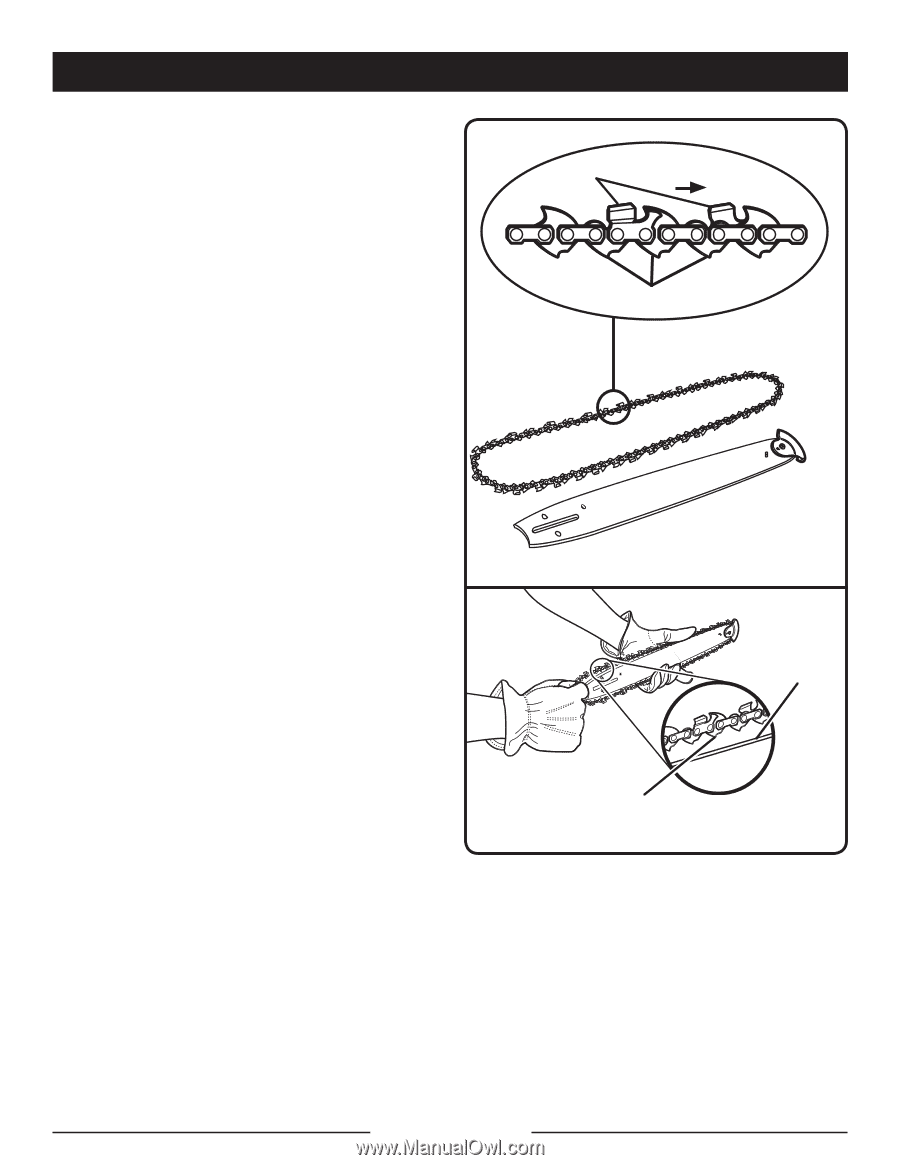
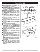
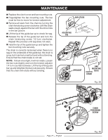
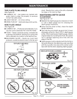
MAINTENANCE n Always place the switch in the STOP " O " position before you work on the saw. n Make sure the chain brake is not set by pulling the chain brake lever/hand guard towards the front handle to the run position. NOTE: When replacing the guide bar and chain, always use the specified bar and chain listed in the Bar and Chain Combinations section later in this manual. n Wear gloves when handling the chain and bar. These components are sharp and may contain burrs. n Remove the bar mounting nuts using the combination wrench provided. n Remove the clutch cover and the outer guide bar plate. n Remove the bar and chain from the mounting surface. n Remove the old chain from the bar. n Lay out the new saw chain in a loop and straighten any kinks. The cutters should face in the direction of chain rotation. If they face backwards, turn the loop over. n Place the chain drive links into the bar groove as shown. n Position the chain so there is a loop at the back of the bar. n Hold the chain in position on the bar and place the loop around the sprocket. n Fit the bar flush against the mounting surface so that the bar studs are in the long slot of the bar. NOTE: When placing the bar on the bar studs, ensure that the adjusting pin is in the chain tension pin hole. n Replace the outer guide bar plate ensuring that the bar pin groove is at the bottom with the upper and lower edges angled away from the guide bar. CUTTERS CHAIN ROTATION CHAIN DRIVE LINKS Fig. 37 BAR GROOVE CHAIN DRIVE LINKS Fig. 38 Page 26 - English
-
 1
1 -
2
-
3
-
4
-
5
-
6
-
7
-
8
-
9
-
10
-
11
-
12
-
13
-
14
-
15
-
16
-
17
-
18
-
19
-
20
-
 21
21 -
 22
22 -
 23
23 -
 24
24 -
 25
25 -
 26
26 -
 27
27 -
 28
28 -
 29
29 -
 30
30 -
 31
31 -
32
-
33
-
34
-
35
-
36
-
37
-
38
-
39
-
40
-
41
-
42
-
43
-
44
-
45
-
46
-
47
-
48
-
49
-
50
-
51
-
52
-
53
-
54
-
55
-
56
-
57
-
58
-
59
-
60
-
61
-
62
-
63
-
64
-
65
-
66
-
67
-
68
-
69
-
70
-
71
-
72
-
73
-
74
-
75
-
76
-
77
-
78
-
79
-
80
-
81
-
82
-
83
-
84
-
85
-
86
-
87
-
88
-
89
-
90
-
91
-
92
-
93
-
94
-
95
-
96
-
97
-
98
-
99
-
100
-
101
-
102
-
103
-
104
-
105
-
106
-
107
-
108
-
109
-
110
-
111
-
112
-
113
-
114
-
115
-
116
-
117
-
118
 |
 |