Ryobi RY40210A User Manual 2 - Page 6
Assembly, Operation - attachments
 |
View all Ryobi RY40210A manuals
Add to My Manuals
Save this manual to your list of manuals |
Page 6 highlights
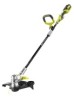
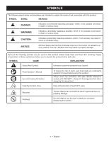
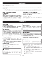
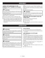
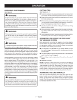
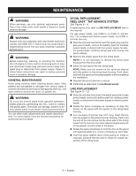
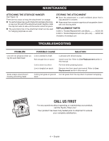
ASSEMBLY JOINING THE POWER HEAD TO THE STRAIGHT SHAFT TRIMMER ATTACHMENT See Figure 3. WARNING: Never attach or adjust any attachment while power head is running. Failure to stop the engine or motor may cause serious personal injury. The straight shaft trimmer attachment connects to the power head by means of a coupler device. Remove the hanger cap from the attachment shaft. Loosen the knob on the coupler of the power head shaft. Push in the button located on the straight shaft trimmer attachment. Align the button with the guide recess on the power head coupler and slide the two shafts together. Rotate attachment shaft until button locks into the positioning hole. NOTE: If the buttons do not release completely in the positioning holes, the shafts are not locked into place. Slightly rotate from side to side until the button is locked into place. Tighten the knob securely. WARNING: Be certain the knob is fully tightened before operating equipment. Check it periodically for tightness during use to avoid serious injury. REMOVING THE ATTACHMENT FROM THE POWER HEAD For removing or changing the attachment: Stop the engine or motor. Loosen the knob. Push in the button and twist the shafts to remove and separate ends. OPERATION WARNING: Do not allow familiarity with this product to make you careless. Remember that a careless fraction of a second is sufficient to inflict serious injury. WARNING: Always wear eye protection with side shields marked to comply with ANSI Z87.1. Failure to do so could result in objects being thrown into your eyes, resulting in possible serious injury. WARNING: Never use blades, flailing devices, wire, or rope on this product. Do not use any attachments or accessories not recommended by the manufacturer of this product. The use of attachments or accessories not recommended can result in serious personal injury. APPLICATIONS You may use this product for the purpose listed below: Trimming grass and weeds from around porches, fences, and decks LINE TRIMMING CUT-OFF BLADE See Figures 4 - 5. The trimmer is equipped with a line trimming cut-off blade on the grass deflector. For best cutting, advance line until it is trimmed to length by the cut-off blade. Advance the line whenever you hear the engine running faster than normal, or when trimming efficiency diminishes. This will maintain best performance and keep the line long enough to advance properly. This trimmer is currently set at the 13 in. cutting swath. To adjust to a cutting swath of 15 in.: Stop the engine or motor. Loosen the blade screw then rotate the line cut-off blade 180°. Tighten the blade screw. 6 - English
-
 1
1 -
 2
2 -
 3
3 -
 4
4 -
 5
5 -
 6
6 -
 7
7 -
 8
8 -
 9
9 -
 10
10 -
 11
11 -
 12
12 -
13
-
14
-
15
-
16
-
17
-
18
-
19
-
20
-
21
-
22
-
23
-
24
-
25
-
26
-
27
-
28
 |
 |