Ryobi RY80588A Operation Manual - Page 11
Assembly
 |
View all Ryobi RY80588A manuals
Add to My Manuals
Save this manual to your list of manuals |
Page 11 highlights
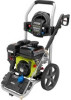
ASSEMBLY PACKING LIST Pressure Washer 25 ft. High Pressure Hose Handle Trigger Handle Spray Wand Quick-Connect Nozzles (4) Trigger Handle Holder Storage Panel Screws (4) Nuts (4) Wheels (2) Axles (2) Hitch Pins (2) Washers (2) 4-Cycle Engine Lubricant (SAE 30 or SAE 10W30) Disposable Funnel Operator's Manual WARNING: If any parts are damaged or missing do not operate this tool until the parts are replaced. Use of this product with damaged or missing parts could result in serious personal injury. WARNING: Do not attempt to modify this tool or create accessories not recommended for use with this tool. Any such alteration or modification is misuse and could result in a hazardous condition leading to possible serious personal injury. WARNING: To prevent accidental starting that could cause serious personal injury, always disconnect the engine spark plug wire from the spark plug when assembling parts. TOOLS NEEDED See Figure 2. The following tools (not included or drawn to scale) are needed for assembly: n Phillips Screwdriver n 10 mm Wrench INSTALLING THE WHEELS See Figure 3 n Locate the axles, hitch pins, washers, and wheels n Slide the axle through the hole in the center of the wheel n Slide the washer onto the axle. n Lift the machine and slide the axle into the wheel mounting hole in the machine base as shown n Push the hitch pin into the hole on the end of the axle to secure the wheel assembly. NOTE: The hitch pin should be pushed into the axle until the center of the pin rests on top of the axle n Repeat with the second wheel. INSTALLING THE HANDLE See Figure 4. CAUTION: Be careful to avoid pinching your fingers or hands when installing the handle onto the frame. Push and hold the button on the handle as you slide the handle into the holes in the frame. NOTE: Before use, pull the handle up until the lock button snaps through the locking slot to secure the handle in place. INSTALLING THE STORAGE PANEL AND TRIGGER HANDLE HOLDER See Figures 5 - 6. n Align the holes in the storage panel with the holes in the handle, as shown. n Insert screws through the left holes (when viewed from front). Install nuts and tighten securely using a Phillips screwdriver and 10 mm wrench (not provided). n Align the trigger handle holder with the holes in the handle and panel on the opposite side, as shown. n Insert the remaining screws through the holes, then install the nuts and tighten securely. CONNECTING THE SPRAY WAND TO THE TRIGGER HANDLE See Figure 7. n Place the threaded end of the spray wand in the connec- tor on the end of the trigger handle. n Fully tighten the connector to secure the spray wand in place. 7 - English
-
 1
1 -
2
-
3
-
4
-
5
-
 6
6 -
 7
7 -
 8
8 -
 9
9 -
 10
10 -
 11
11 -
 12
12 -
 13
13 -
 14
14 -
 15
15 -
 16
16 -
17
-
18
-
19
-
20
-
21
-
22
-
23
-
24
-
25
-
26
-
27
-
28
-
29
-
30
-
31
-
32
-
33
-
34
-
35
-
36
-
37
-
38
-
39
-
40
-
41
-
42
-
43
-
44
-
45
-
46
-
47
-
48
-
49
-
50
-
51
-
52
-
53
-
54
-
55
-
56
 |
 |
