Samsung CS-15K5ML Service Manual - Page 10
Samsung CS-15K5ML Manual
 |
View all Samsung CS-15K5ML manuals
Add to My Manuals
Save this manual to your list of manuals |
Page 10 highlights
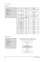
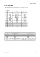
Alignment and Adjustments PIN NO 33 34 35 36 37 38 39 40 41 42 43 44 45 46 47 48 49 50 51 52 53 54 55 56 57 58 59 60 61 62 63 64 SYMBOL HOUT FBISO QSSO/AMOUT EHTO PLLIF IFVO/SVO/DVBO VP1 CVBS1 GND CVBS/Y C SVM INSSW2 R2/VIN G2/YIN B2/UIN BCLIN BLKIN RO GO BO VDDA VPE VDDC OSCGND XTLIN XTLOUT RESET VDDP P1.0/INT1 P1.1/T0 P1.2/INTO horizontal output PIN FUNCTION CHECK VOLTAGE S-By P-On flyback input/sandcastle output QSS intercarrier output/AM output in stereo applications or deemphasis(front-end audio out)/AM output in mono applications EHT/overvoltage protection input IF-PLL loop filter AGC sound IF/inter-external AGC for DVB applications main supply voltage TV processor internal CVBS input ground for TV processor CVBS3/Y input chroma input scan velocity modulation output 2nd RGB/YUV insertion input 2nd R input/V(R-Y) input PR input 2nd G input/Y input 2nd B input/U(B-Y) input PB input beam current limiter input black current input/V-guard input Red output Green output Blue output analog supply of Teletext decoder and digital supply of TVprocessor(3.3 V) OTP Progamming Voltage digital supply to core(3.3 V) oscillator ground supply crystal oscillator input crystal oscillator output reset digital supply to peryipher(+3.3 V) port 1.0 or external interrupt 1 input port 1.1 or Counter/Timer 0 input port 1.2 or external interrupt 0 input 2-9 Samsung Electronics
-
 1
1 -
2
-
3
-
4
-
 5
5 -
 6
6 -
 7
7 -
 8
8 -
 9
9 -
 10
10 -
 11
11 -
 12
12 -
 13
13 -
 14
14 -
 15
15 -
16
-
17
-
18
-
19
-
20
-
21
-
22
-
23
-
24
-
25
-
26
-
27
-
28
-
29
-
30
-
31
-
32
-
33
-
34
-
35
-
36
-
37
-
38
-
39
-
40
-
41
-
42
 |
 |
