Samsung DV22K6800EW/AC User Manual - Page 20
CAUTION, WARNING, For a 4-wire system
 |
View all Samsung DV22K6800EW/AC manuals
Add to My Manuals
Save this manual to your list of manuals |
Page 20 highlights
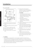
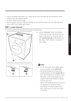
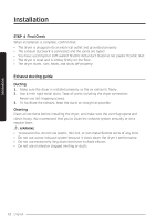
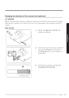
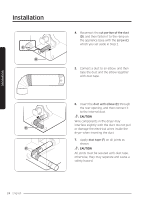
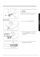
Installation Installation For a 4-wire system 1. Remove the external ground connector's screw, and connect the ground wire (green or unwrapped) of A the power cable to the screw. CAUTION D B E C F A. Center silver-colored terminal block screw B. Neutral grounding wire (white or green/ yellow) C. ¾" (1.9 cm) UL-listed strain relief D. Neutral wire (white or center wire) E. External ground connector F. Green or bare copper wire of power cord • To connect the ground wire to the neutral position without through contact A (cabinet ground), contact a technician. This is not user serviceable. • Ring-type terminals are recommended. If using strap terminals, make sure they are tightened. 2. Loosen or remove the screws from the center terminal block. 3. Connect the neutral wire (white or center wire) and ground wire (white) to the center, silver-colored terminal screw of the terminal block. Tighten the screw. 4. Connect the other wires to the outer terminal block screws. Tighten the screws. 5. Tighten the strain relief screws. 6. Insert the tab of the terminal block cover into the rear panel of the dryer. Then, secure the cover with a holddown screw. WARNING • All U.S. models are designed for a 3-wire system connection. The dryer frame is grounded to the neutral conductor at the terminal block. A 4-wire system connection is required for new or remodeled construction, mobile homes, or if local codes do not permit grounding through neutral. If you use the 4-wire system, you cannot ground the dryer frame to the neutral conductor at the terminal block. • Remove the terminal block cover plate. 20 English
-
 1
1 -
2
-
3
-
4
-
5
-
6
-
7
-
8
-
9
-
10
-
11
-
12
-
13
-
14
-
 15
15 -
 16
16 -
 17
17 -
 18
18 -
 19
19 -
 20
20 -
 21
21 -
 22
22 -
 23
23 -
 24
24 -
 25
25 -
26
-
27
-
28
-
29
-
30
-
31
-
32
-
33
-
34
-
35
-
36
-
37
-
38
-
39
-
40
-
41
-
42
-
43
-
44
-
45
-
46
-
47
-
48
-
49
-
50
-
51
-
52
-
53
-
54
-
55
-
56
-
57
-
58
-
59
-
60
-
61
-
62
-
63
-
64
-
65
-
66
-
67
-
68
-
69
-
70
-
71
-
72
-
73
-
74
-
75
-
76
-
77
-
78
-
79
-
80
-
81
-
82
-
83
-
84
-
85
-
86
-
87
-
88
-
89
-
90
-
91
-
92
-
93
-
94
-
95
-
96
-
97
-
98
-
99
-
100
-
101
-
102
-
103
-
104
-
105
-
106
-
107
-
108
-
109
-
110
-
111
-
112
-
113
-
114
-
115
-
116
-
117
-
118
-
119
-
120
-
121
-
122
-
123
-
124
-
125
-
126
-
127
-
128
-
129
-
130
-
131
-
132
-
133
-
134
-
135
-
136
-
137
-
138
-
139
-
140
-
141
-
142
-
143
-
144
-
145
-
146
-
147
-
148
-
149
-
150
-
151
-
152
-
153
-
154
-
155
-
156
-
157
-
158
-
159
-
160
-
161
-
162
-
163
-
164
-
165
-
166
-
167
-
168
-
169
-
170
-
171
-
172
-
173
-
174
-
175
-
176
-
177
-
178
-
179
-
180
 |
 |
