Samsung HT-DB120 User Manual (user Manual) (ver.1.0) (English) - Page 8
Connecting the FM and AM(MW) Antennas, Connecting the Video to TV
 |
View all Samsung HT-DB120 manuals
Add to My Manuals
Save this manual to your list of manuals |
Page 8 highlights
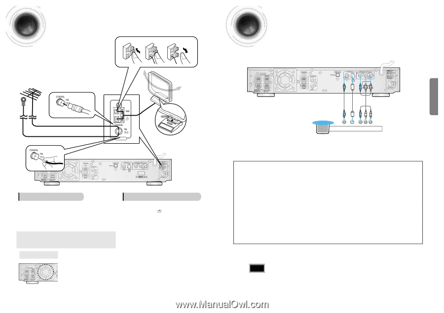
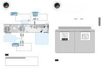
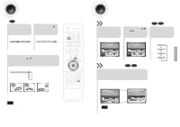
Connecting the FM and AM(MW) Antennas If AM reception is poor, connect an 1 outdoor AM antenna(not supplied). 2 3 Connecting the Video to TV CONNECTIONS If FM reception is poor, connect an outdoor FM antenna (not supplied). AM Loop Antenna (supplied) FM Antenna (supplied) ANTENNA Snap the tabs on the loop into the slots of the base to assemble the AM loop antenna. VOLTAGE SELECTOR FM antenna connection AM(MW) antenna connection 1. Connect the FM antenna supplied to the FM 75Ω COAXIAL terminal as a temporary measure. 2. Slowly move the antenna wire around until you find a location where reception is good, then fasten it to a wall or other rigid surface. • If reception is poor, connect an outdoor antenna. Before attaching a 75Ω coaxial cable (with a standard type connector), disconnect the supplied FM antenna. 1. Connect the AM loop antenna supplied to the AM and terminals. 2. If reception is poor, connect an outdoor single vinyl-covered wire to the AM terminal. (Keep the AM loop antenna connected). Cooling Fan 13 The cooling fan dissipates the heat generated inside the unit so that the unit can be operated normally. The cooling fan is activated automatically to supply cool air to the unit. Please observe the following cautions for your safety. • Make sure the unit is well-ventilated. If the unit has poor ventilation, the temperature inside the unit could rise and may damage it. • Do not obstruct the cooling fan or ventilation holes. (If the cooling fan or ventilation holes are covered with a newspaper or cloth, heat may build up inside the unit and fire may result.) VOLTAGE SELECTOR TV Composite S-Video Video Component Video * Depending on your TV, Component Video input connectors may be marked as DVD Video input connectors. Composite Video (Good Quality) Connect the supplied video cable from the VIDEO OUT jack on the back panel of the system to the VIDEO IN jack on your television. S-Video (Better Quality) If you television is equipped with an S-Video input, connect an S-Video cable (not supplied) from the S-VIDEO OUT jack on the back panel of the system to the S-VIDEO IN jack on your television. Component Video (Best Quality) If your television is equipped with Component Video inputs, connect a component video cable (not supplied) from the Pr, Pb and Y jacks on the back panel of the system to the corresponding jacks on your television. Note • When the Progressive scan mode is selected, the VIDEO and S-VIDEO outputs do not feed any signals. 14
-
 1
1 -
2
-
 3
3 -
 4
4 -
 5
5 -
 6
6 -
 7
7 -
 8
8 -
 9
9 -
 10
10 -
 11
11 -
 12
12 -
 13
13 -
14
-
15
-
16
-
17
-
18
-
19
-
20
-
21
-
22
-
23
-
24
-
25
-
26
-
27
-
28
-
29
-
30
-
31
 |
 |