Samsung HT-DB660 User Manual (user Manual) (ver.1.0) (English) - Page 6
Description - manual
 |
View all Samsung HT-DB660 manuals
Add to My Manuals
Save this manual to your list of manuals |
Page 6 highlights
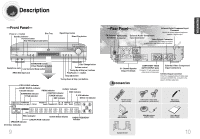
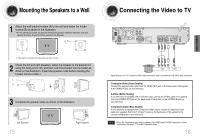
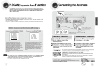
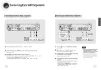
PREPARATION Description -Front Panel- Power ( ) button Disc Tray Standby indicator Function button Rear Reflecting Surround System Open/Close button Direct Play button -Rear Panel- External Digital Component Input Connector Use this to connect external equipment FM Antenna AM Antenna External Audio Component capable of digital output. Connector Connector Input Connector Video Output Connector Connect the TV's video input jacks (VIDEO IN) to the VIDEO OUT connector. SURROUND button / Virtual Headphone button Headphone Jack Live Surround Mode button RRSS MIC Input Jack Disc Change button Volume control Tuning Up & Skip ( ) buttons Play/Pause ( ) button Stop ( ) button Tuning Down & Skip ( ) buttons PRO LOGIC indicator DOLBY DIGITAL indicator REPEAT indicator P.SCAN indicator PRGM indicator SURROUND indicator CHAPTER indicator DISC indicator TITLE indicator TUNER indicator 5.1CH indicator DSP indicator DISC(1~5) indicator EX SURROUND CMX L CR SW LS S RS LINEAR PCM PBC PRGM A B REPEAT 1 TITLE CHAP TUNED ST D S P ALL DISC TITLE PBC CHAP PRGM RDS RT TA 5.1 CH kHz MHz PBC indicator System Status Display LINEAR PCM indicator SPEAKER indicator DTS Disc indicator RADIO FREQUENCY indicator 9 5.1 Channel Speaker Output Terminals Accessories COMPONENT VIDEO External Video Component OUTPUT/INPUT jacks Input Connectors Connect a TV with component video inputs to these jacks. S-Video Output Connector If the TV is equipped with an S-Video input connector (S-VIDEO IN), connect it to the player's S-Video output jack. Remote Control (AH59-01225H) Audio Cable / Video Cable (AH39-40001U) / (AH39-40001V) FM Antenna (AH42-00004A) AM Antenna (AH42-20001P) Speaker Bracket RRSS Microphone (AH59-01183D) User's Manual (AH68-01328R) 10
-
 1
1 -
 2
2 -
 3
3 -
 4
4 -
 5
5 -
 6
6 -
 7
7 -
 8
8 -
 9
9 -
 10
10 -
 11
11 -
 12
12 -
13
-
14
-
15
-
16
-
17
-
18
-
19
-
20
-
21
-
22
-
23
-
24
-
25
-
26
-
27
-
28
-
29
-
30
-
31
-
32
-
33
-
34
-
35
-
36
-
37
-
38
 |
 |
