Samsung LNS3241D User Manual (ENGLISH) - Page 12
Connecting a Camcorder (LN-S3241D/LN-S4041D), Connecting a DVD Player, LN-S3241D/LN-S4041D - dvi
 |
UPC - 036725232419
View all Samsung LNS3241D manuals
Add to My Manuals
Save this manual to your list of manuals |
Page 12 highlights
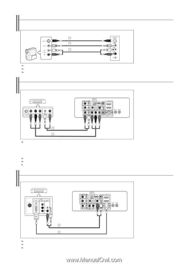
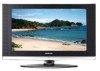
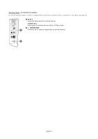
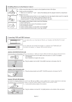
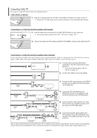
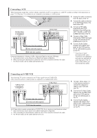
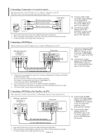
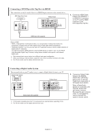
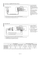
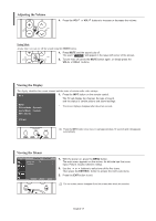
Connecting a Camcorder (LN-S3241D/LN-S4041D) The side panel jacks on your TV make it easy to connect a camcorder to your TV. They allow you to view the camcorder tapes without using a VCR Camcorder 1 S-Video Cable (Not supplied) or 1 Video Cable (Not supplied) 2 Audio Cable (Not supplied) TV Side Panel Each external input source device has a different back panel configuration. When connecting an external device, match the color of the connection terminal to the cable. For 40 inch model, use the cables with the ferrite core. Connecting a DVD Player The rear panel jacks on your TV make it easy to connect a DVD player to your TV. DVD Player Rear Panel TV Rear Panel 2 Audio Cable (Not supplied) 1 Component Cable (Not supplied) Component video separates the video into Y (Luminance (brightness)), Pb (Blue) and Pr (Red) for enhanced video quality. Be sure to match the component video and audio connections. For example, if connecting the video cable to COMPONENT IN, connect the audio cable to COMPONENT IN also. Each external input source device has a different back panel configuration. When connecting an external device, match the color of the connection terminal to the cable. For 40 inch model, use the cables with the ferrite core. Connecting a DVD Player/Set-Top Box via DVI This connection can only be made if there is a DVI Output connector on the external device. DVD Player / Set-Top Box TV Rear Panel 2 Audio Cable (Not supplied) 1 DVI to HDMI Cable (Not supplied) 1. Connect a Video Cable (or S-Video Cable )between the AV IN2 [VIDEO] (or S-VIDEO) jack on the TV and the VIDEO OUT jack on the camcorder. 2. Connect Audio Cables between the AV IN2 [R-AUDIO-L] jacks on the TV and the AUDIO OUT jacks on the camcorder. 1. Connect a Component Cable between the COMPONENT IN [PR, PB, Y] jacks on the TV and the COMPONENT [Y, PB, PR] jacks on the DVD player. 2. Connect Audio Cables between the COMPONENT IN [R-AUDIO-L] jacks on the TV and the AUDIO OUT jacks on the DVD player. 1. Connect a DVI to HDMI Cable or DVI-HDMI Adapter between the HDMI/DVI IN 1 or HDMI/DVI IN 2 connector on the TV and the DVI connector on the DVD player/Set-Top Box. 2. Connect Audio Cables between the DVI IN [R-AUDIO-L] jack on the TV and the AUDIO OUT jacks on the DVD player/ Set-Top Box. Each external input source device has a different back panel configuration. When connecting an external device, match the color of the connection terminal to the cable. For 40 inch model, use the cables with the ferrite core. English-10
-
 1
1 -
2
-
3
-
4
-
5
-
6
-
 7
7 -
 8
8 -
 9
9 -
 10
10 -
 11
11 -
 12
12 -
 13
13 -
 14
14 -
 15
15 -
 16
16 -
 17
17 -
18
-
19
-
20
-
21
-
22
-
23
-
24
-
25
-
26
-
27
-
28
-
29
-
30
-
31
-
32
-
33
-
34
-
35
-
36
-
37
-
38
-
39
-
40
-
41
-
42
-
43
-
44
-
45
-
46
-
47
-
48
-
49
-
50
-
51
-
52
-
53
-
54
-
55
-
56
-
57
-
58
-
59
-
60
-
61
-
62
-
63
-
64
-
65
-
66
-
67
-
68
-
69
-
70
-
71
-
72
-
73
-
74
-
75
-
76
-
77
-
78
-
79
-
80
-
81
-
82
-
83
-
84
-
85
-
86
-
87
-
88
-
89
-
90
-
91
-
92
-
93
-
94
-
95
-
96
-
97
-
98
-
99
-
100
-
101
-
102
-
103
-
104
-
105
-
106
-
107
-
108
-
109
-
110
-
111
-
112
-
113
-
114
-
115
-
116
-
117
-
118
-
119
-
120
-
121
-
122
-
123
-
124
-
125
-
126
-
127
-
128
-
129
-
130
-
131
-
132
-
133
-
134
-
135
-
136
-
137
-
138
-
139
-
140
-
141
-
142
-
143
-
144
-
145
-
146
-
147
-
148
-
149
-
150
-
151
-
152
-
153
-
154
-
155
-
156
-
157
-
158
-
159
-
160
-
161
-
162
-
163
-
164
-
165
-
166
-
167
-
168
-
169
-
170
-
171
-
172
-
173
-
174
-
175
-
176
-
177
-
178
-
179
 |
 |