Samsung STP-103P User Manual - Page 28
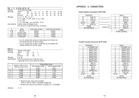
Parallel Interface Connector Specification, PINE MALE, Control Command, ESC p, DLE DC4 n m t, Bell n
 |
View all Samsung STP-103P manuals
Add to My Manuals
Save this manual to your list of manuals |
Page 28 highlights
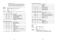
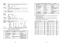
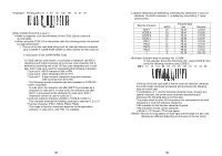
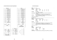
2) Parallel Interface Connector Specification PRINTER 1 /STROBE (I/O) 2 DATA0 (I/O) 3 DATA1 (I/O) 4 DATA2 (I/O) 5 DATA3 (I/O) 6 DATA4 (I/O) 7 DATA5 (I/O) 8 DATA6 (I/O) 9 DATA7 (I/O) 10 /ACK (I) 11 BUSY (I) 12 PE (I) 13 SLCT 15 /ERROR (I) 22~25 GND FGND HOST 1 /STROBE (I/O) 2 DATA0 (I/O) 3 DATA1 (I/O) 4 DATA2 (I/O) 5 DATA3 (I/O) 6 DATA4 (I/O) 7 DATA5 (I/O) 8 DATA6 (I/O) 9 DATA7 (I/O) 10 /ACK (I) 11 BUSY (I) 12 PE (I) 13 SLCT 15 /ERROR (I) 16 /INIT (O) 18~25 GND FGND 25 PINE MALE * RJ11 6P 6 22 SG ---- 1 GND 14 SOL1 ---- 2 SOL1 16 COMPS/W ---- 3 COMPS/W 17 SLCT ---- 4 SLCT 5 NC 22 SG ---- 6 GND 25 PINE MALE 1 54 3) Control Command ESC p m t1 t2 [Name] Generate pulse. [Format] ASCII ESC p m t1 t2 Hex 1B 70 m t1 t2 Decimal 27 112 m t1 t2 [Range] m = 0, 48 0 ≤ t1 ≤ 255, 0 ≤ t2 ≤ 255 [Description] Outputs the pulse specified by t1 and t2 to connector pin m as follows : m=0 Connector pin : Drawer kick-out connector pin 2. [Details] The pulse ON time is [t1*2ms] and the OFF time is [t2*2ms]. If t2 ≤ t1, the OFF time is [t2*2ms]. [Reference] DLE DC4 DLE DC4 n m t [Name] Generate pulse at real-time. [Format] ASCII DLE DC4 n m t Hex 10 14 n m t Decimal 16 20 n m t [Range] n=1, m=0 1 ≤ t ≤ 8 [Description] Outputs the pulse specified by t to connector pin m as follows : m=0 Connector pin : Drawer kick-out connector pin 2. The pulse ON time is [t*100ms] and the OFF time is [t*100ms]. [Reference] ESC p Bell n [Name] [Format] [Range] [Description] Select bell on time. ASCII Bell t Hex 07 t (1e t) Decimal 07 t (30 t) t = 1~30 The pulse ON time is [t*100ms] and the OFF time is [t*100ms]. 55
-
 1
1 -
2
-
3
-
4
-
5
-
6
-
7
-
8
-
9
-
10
-
11
-
12
-
13
-
14
-
15
-
16
-
17
-
18
-
19
-
20
-
21
-
22
-
 23
23 -
 24
24 -
 25
25 -
 26
26 -
 27
27 -
 28
28
 |
 |
