Samsung WF365BTBGSF/A2 User Manual Tech Manual (English, French, Spanish) - Page 18
Problem Checking And Method Of Pcb, Wf364, Wf361*/wf363*/wf365, Warning
 |
View all Samsung WF365BTBGSF/A2 manuals
Add to My Manuals
Save this manual to your list of manuals |
Page 18 highlights
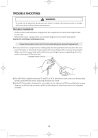
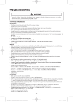
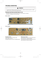
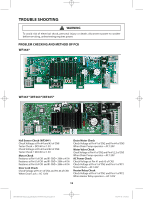
TROUBLE SHOOTING WARNING To avoid risk of electrical shock, personal injury or death; disconnect power to washer before servicing, unless testing requires power. PROBLEM CHECKING AND METHOD OF PCB WF364* WF361*/WF363*/WF365* Hall Sensor Check (WF364*) Check Voltage at Pin #4 and #3 of CN8 Tester Check = DC0.6V or 1.3V Check Voltage at Pin #4 and #2 of CN8 Tester Check = DC0.6V or 1.3V Motor Check Resistance at Pin #1 of CN1 and R1-GND = 280# or 470# Resistance at Pin #2 of CN1 and R1-GND = 280# or 470# Resistance at Pin #3 of CN1 and R1-GND = 280# or 470# Door Lock Check Check Voltage at Pin #1 of CN2 and Pin #6 of CN5 When Door Lock = AC 120V Drain Motor Check Check Voltage at Pin #1 of CN2 and Pin #4 of CN5 When Drain Pump operates = AC 120V Water Valve Check Check Voltage at Pin #1 of CN2 and Pin #1,2,3 of CN5 When Drain Pump operates = AC 120V AC Power Check Check Voltage at Pin #1 and #3 of CN2 Check Voltage at Pin #1 of CN2 and Pin #1 of RY1 Tester Check = AC 120V Heater Relay Check Check Voltage at Pin #1 of CN2 and Pin #1 of RY2 When Heater Relay operates = AC 120V 18
-
 1
1 -
2
-
3
-
4
-
5
-
6
-
7
-
8
-
9
-
10
-
11
-
12
-
 13
13 -
 14
14 -
 15
15 -
 16
16 -
 17
17 -
 18
18 -
 19
19 -
 20
20 -
 21
21 -
 22
22 -
 23
23 -
24
-
25
-
26
-
27
-
28
-
29
-
30
-
31
-
32
-
33
-
34
-
35
-
36
-
37
-
38
-
39
-
40
-
41
-
42
-
43
-
44
-
45
-
46
-
47
-
48
-
49
-
50
-
51
-
52
-
53
-
54
-
55
-
56
-
57
-
58
-
59
-
60
-
61
-
62
-
63
-
64
-
65
-
66
-
67
-
68
-
69
-
70
-
71
-
72
 |
 |