SanDisk SDCFRX4-2048-901 Product Manual - Page 24
Interface Description, SanDisk CompactFlash Card OEM Product Manual, Signal Name, Description
 |
UPC - 619659028954
View all SanDisk SDCFRX4-2048-901 manuals
Add to My Manuals
Save this manual to your list of manuals |
Page 24 highlights
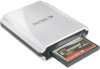
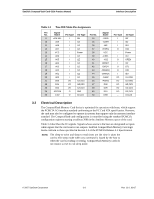
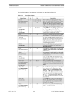
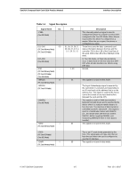
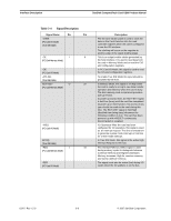
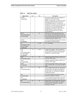
Interface Description SanDisk CompactFlash Card OEM Product Manual Table 3-4 Signal Description Signal Name Dir. Pin -IOWR (PC Card I/O Mode) (True IDE Mode) -OE I 9 (PC Card Memory Mode) -OE (PC Card I/O Mode) -ATA SEL (True IDE Mode) RDY/-BSY O 37 (PC Card Memory Mode) -IREQ (PC Card I/O Mode) INTRQ (True IDE Mode) -REG I 44 (PC Card Memory Mode) -REG (PC Card I/O Mode) Description The I/O write strobe pulse is used to clock I/O data on the Card Data bus into the card controller registers when the card is configured to use the I/O interface. The clocking will occur on the negative to positive edge of the signal (trailing edge). This is an output enable strobe generated by the host interface. It is used to read data from the card in Memory Mode and to read the CIS and configuration registers. In PC Card I/O Mode, this signal is used to read the CIS and configuration registers. To enable True IDE Mode this input should be grounded by the host. In Memory Mode, this signal is set high when the card is ready to accept a new data transfer operation and held low when the card is busy. The host memory card socket must provide a pull-up resistor. At power up and at reset, the RDY/-BSY signal is held low (busy) until the card has completed its power up or reset function. No access of any type should be made to the card during this time. The RDY/-BSY signal is held high (disabled from being busy) whenever the following condition is true: The card has been powered up with +RESET continuously disconnected or asserted. I/O Operation-After the card has been configured for I/O operation, this signal is used as an interrupt request. This line is strobed low to generate a pulse mode interrupt or held low for a level mode interrupt. In True IDE Mode, this signal is the active high Interrupt Request to the host. This Attribute Memory Select signal is used during memory cycles to distinguish between Common Memory and Register (Attribute) Memory accesses: High for common memory, and low for attribute memory. The signal must also be active (low) during I/O cycles when the I/O address is on the bus. 02/07, Rev. 12.0 3-6 © 2007 SanDisk Corporation
-
 1
1 -
2
-
3
-
4
-
5
-
6
-
7
-
8
-
9
-
10
-
11
-
12
-
13
-
14
-
15
-
16
-
17
-
18
-
 19
19 -
 20
20 -
 21
21 -
 22
22 -
 23
23 -
 24
24 -
 25
25 -
 26
26 -
 27
27 -
 28
28 -
 29
29 -
30
-
31
-
32
-
33
-
34
-
35
-
36
-
37
-
38
-
39
-
40
-
41
-
42
-
43
-
44
-
45
-
46
-
47
-
48
-
49
-
50
-
51
-
52
-
53
-
54
-
55
-
56
-
57
-
58
-
59
-
60
-
61
-
62
-
63
-
64
-
65
-
66
-
67
-
68
-
69
-
70
-
71
-
72
-
73
-
74
-
75
-
76
-
77
-
78
-
79
-
80
-
81
-
82
-
83
-
84
-
85
-
86
-
87
-
88
-
89
-
90
-
91
-
92
-
93
-
94
-
95
-
96
-
97
-
98
-
99
-
100
-
101
-
102
-
103
-
104
-
105
-
106
-
107
-
108
 |
 |