Sanyo DP55441 Owners Manual - Page 9
Getting Started-controls And Jacks - firmware
 |
View all Sanyo DP55441 manuals
Add to My Manuals
Save this manual to your list of manuals |
Page 9 highlights
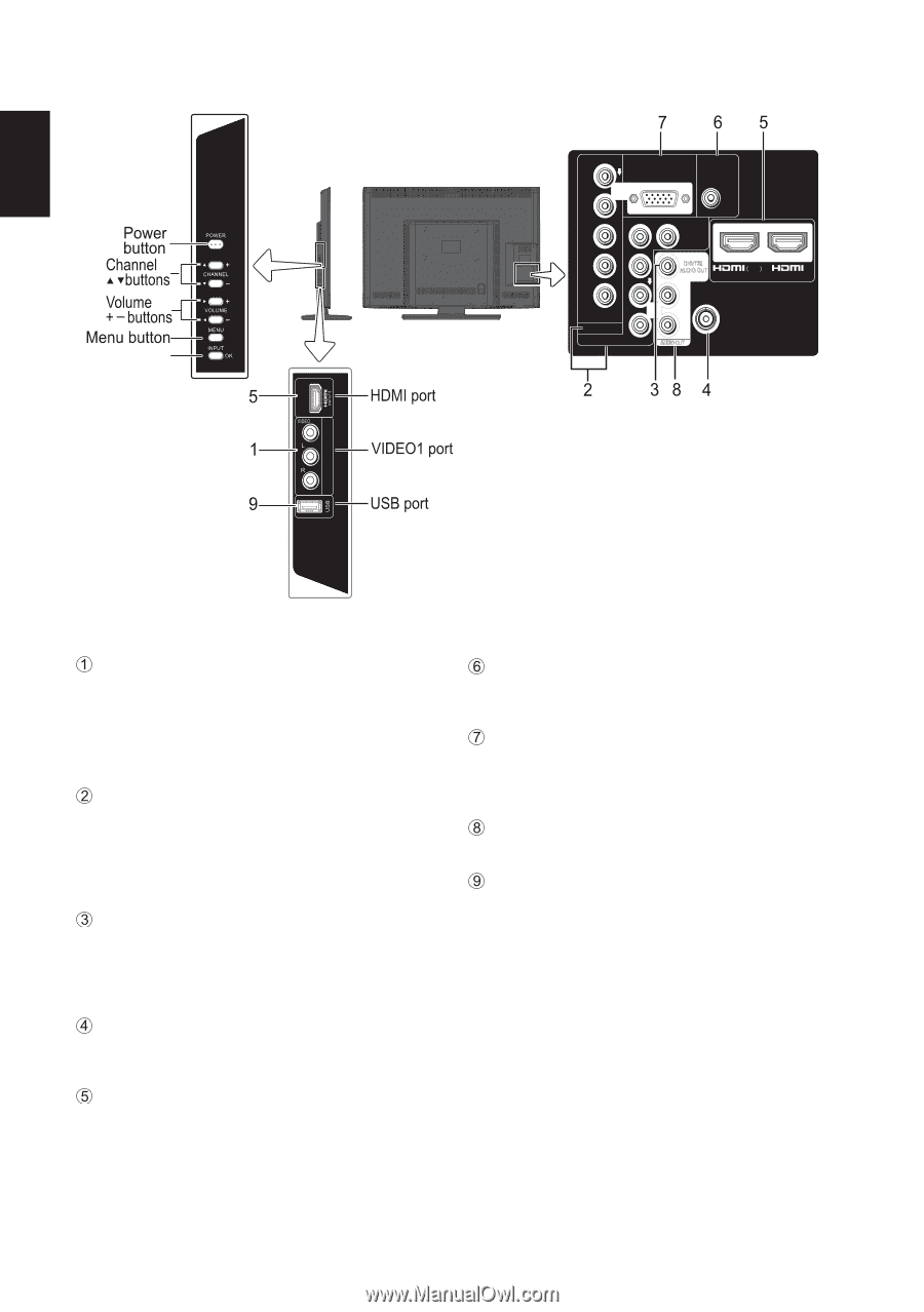
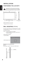
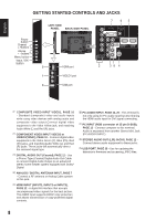
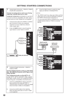
English V DEO 1 NPUT GETTING STARTED-CONTROLS AND JACKS Input / OK button LEFT-SIDE PANEL BACK-SIDE PANEL Y PC INPUT PC AUDIO INPUT Pb Pr Pb L Pr R L R DEO3 INPUT V DEO2 INPUT Y/VIDEO DV L INPUT1 INPUT2 ANT R COMPOSITE VIDEO INPUT VIDEO1, PAGE 10 - Standard (composite) video and audio inputs while using video devices with analog audio and composite video output.Connect digital video equipment to the Video Yellow jack, and matching Audio White (L) and Red (R) jacks. COMPONENT VIDEO INPUT VIDEO2 or VIDEO3(YPbPr), PAGE 10 - Connect digital video equipment to the Video Green (Y), Blue (Pb), Red (Pr) jacks, and matching Audio White (L) and Red (R) jacks. These jacks will automatically detect the received signal type. DIGITAL AUDIO OUT (Coaxial), PAGE 12 - Use a Phono-Type (Coaxial) Digital Audio Out Cable to connect Digital Audio Output to an advanced stereo home theater system equipped with Dolby® Digital. ANALOG / DIGITAL ANTENNA INPUT, PAGE 7 - Connect a RF antenna or Analog Cable system to this jack. HDMI INPUT (INPUT1, INPUT2 or INPUT3), PAGE 12 - A digital AV interface that accepts uncompressed video signals for the best picture. This HDMI input supports HDCP copy protection and allows transmission of copy-protected digital contents. PC AUDIO INPUT, PAGE 12, 20 - This terminal is not only using for PC audio input but also sharing the HDMI audio input for DVI signal connecting. PC INPUT (RGB connector of 15 pin D-SUB), PAGE 13 - Connect computer to this terminal. Audio is separated from another Stereo Mini Jack (PC AUDIO INPUT). STEREO AUDIO OUT (L/R) JACKS, PAGE 12 Connect stereo audio equipment to these jacks. USB PORT, PAGE 25 - Use for updating the television's firmware and accessing JPEG files. 8
-
 1
1 -
2
-
3
-
 4
4 -
 5
5 -
 6
6 -
 7
7 -
 8
8 -
 9
9 -
 10
10 -
 11
11 -
 12
12 -
 13
13 -
 14
14 -
15
-
16
-
17
-
18
-
19
-
20
-
21
-
22
-
23
-
24
-
25
-
26
-
27
-
28
-
29
-
30
-
31
-
32
 |
 |