Sanyo EM-V5404SW Service Manual - Page 3
Description & Function Of Com
 |
View all Sanyo EM-V5404SW manuals
Add to My Manuals
Save this manual to your list of manuals |
Page 3 highlights
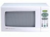
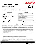
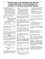
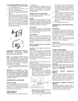
TO PERFORM MICROWAVE LEAKAGE CHECK: 1. Fill 275 milliliters or 9 ounces of tap water in a 2 cup measuring cup. 2. Place the container in the center of the oven cavity on the glass tray. 3. Set power control for microwave "Cook" (high) or 100% operation. Set timer for 3 minutes. 4. Close the door securely and start the oven. 5. Perform the proper adjustment and operations check with the microwave leakage meter (refer to the operation instructions with the meter). Check the oven by moving the probe, starting at the top right-hand side of the door, clockwise no faster than one inch per second, back to the starting position. Also, a check over the entire visual screen must be made. Probe Speed: One inch per second (max.) IMPORTANT: MICROWAVE LEAKAGE CHECK MUST BE PERFORMED ON THE REAR VENTS AND SIDE VENTS. NOTE: THE METER PROBE MUST BE HELD APPROXIMATELY TWO INCHES FROM THE POINT OF MEASUREMENT. THIS IS ACCOMPLISHED BY THE USE OF A TWOINCH (5 cm) PLASTIC SPACER THAT IS SUPPLIED WITH THE METER. IT IS NORMALLY ATTACHED TO THE PROBE. 6. The maximum allowable microwave leak- age level is 5mW/cm2 by government standard. IMPORTANT: IF THE READING IS OVER 2 mW/cm2, REFER TO THE DOOR AND INTER- LOCK ADJUSTMENTS SECTION IN THIS MAN- UAL. THE OF LESS DOOR THAN IS 1 DmEWSI/GcmN2E,DAFDOJRUSLETMAKEANGTSE STOHOBUELLDOWBE1MmAWD/EcmT2O. BRING ALL READINGS MAGNETRON FAILURE MODES no heating power. An open filament lead or "dead" filament transformer will give the same indication as an open filament in the magnetron. This possibility should be eliminated before the magnetron is considered open. INTERNAL PLATE CATHODE SHORT A shorted magnetron will give the same indications as the loss of vacuum. MODING Moding occurs when the magnetron momentarily operates at a different frequency and a higher voltage than designed. Moding results in low heating power. Moding is usually caused by the cathode losing emission characteristics. LOW POWER Low emission will result in low cooking power. Food will require a longer than normal cooking time. It can be detected by a lower than normal water temperature rise. LOW EMISSION Caused by "wearout" of the emission characteristics of the directly heated cathode. The tube current does not get high enough to cause the tube to oscillate with normal line voltage. Everything will appear normal, but the tube will not heat. SAFETY PRECAUTIONS FOR DISASSEMBLY AND REPAIR -Cautions to be observed when troubleshooting. Unlike many other appliances, the microwave oven is a high-voltage, high-current piece of equipment. It is completely safe during normal operation. However, carelessness in servicing the oven can result in an electric shock or possible danger from a short circuit. You are asked to observe the following precautions carefully. (1) Always remove the power plug from the outlet before servicing. (2) Use an insulated screwdriver and wear rubber gloves when servicing the high voltage side. (3) Discharge the high voltage capacitor before touching any oven components or wiring. 1. Check the grounding. Do not operate on a 2-wire extension cord. The microwave oven is designed to be used when grounded. It is imperative, therefore, to make sure it is grounded properly before beginning repair work. high voltage capacitor. When replacing or checking parts, create a short between oven chassis and the negative high terminal of the high voltage capacitor, by using a properly insulated screwdriver to discharge it. (4) When the 20 Amp. fuse is blown out due to the operation of the monitor switch, replace primary and secondary interlock switches, monitor switch and relay 2. (5) After repair or replacement of parts, make sure that the screws are properly tightened, and all electrical connections are tightened. (6) Do not operate without cabinet. DESCRIPTION & FUNCTION OF COMPONENTS FAN MOTOR The fan motor drives a blower fan which draws cool air through the back of the oven. This cool air is directed through the air ducts surrounding the magnetron tube to cool the magnetron. Some of the air is then exhausted directly through the bottom vents. However, a portion of this air is channeled through the cavity to remove the steam and vapors given off from heating food. OVEN LIGHT The oven light illuminates the interior of the cavity so the food can be visually examined through the door. POWER TRANSFORMER The purpose of the power transformer is to provide the filament voltage for heating the magnetron filaments as well as to produce the high voltage needed for magnetron tube operation. During a cook cycle, the ,120 Volts AC applied to the primary winding is converted to approximately 3.22 Volts AC on the filament winding. The same 120 Volts AC primary input is converted to approximately 2070 Volts AC on the high voltage secondary winding of the power transformer. CAUTIONS: AFTER REMOVING THE CABINET, DISCHARGE THE CAPACITOR BY PLACING AN INSULATED SCREWDRIVER ACROSS THE TERMINALS. PRIMARY (UPPER) INTERLOCK SWITCH The primary protective switch (interlock) is activated by the latch when the door is closed. The switch, in the open position when the door is open, interrupts the current to the magnetron. Closing the door will close the interlock switch and normal operations can be continued. LOSS OF VACUUM SECONDARY (LOWER) INTERLOCK This is a case where the tube has had the vac- SWITCH uum envelope destroyed and air has entered The secondary protective interlock switch is the tube. This will cause internal arcing. With Short located behind the front control panel and is acti- continued use, the transformer will eventually vated when the door is closed. When the door is fail and the circuit fuse will blow. open, this switch will interrupt the circuit. 2. Warning about the electric charge in OPERATION FAULTS the high voltage capacitor. OPEN FILAMENTS For about 60 seconds after the operation A magnetron with an open filament will produce stops, an electric charge remains in the 3
-
 1
1 -
 2
2 -
 3
3 -
 4
4 -
 5
5 -
 6
6 -
 7
7 -
 8
8 -
 9
9 -
10
-
11
-
12
-
13
-
14
-
15
 |
 |