Sanyo EM-V5404SW Service Manual - Page 5
High Voltage Component Opera
 |
View all Sanyo EM-V5404SW manuals
Add to My Manuals
Save this manual to your list of manuals |
Page 5 highlights
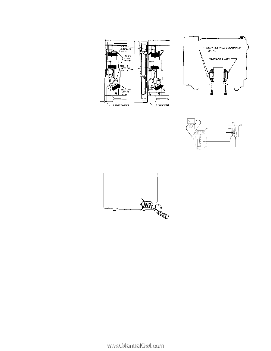
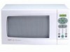
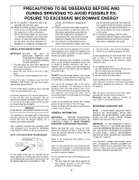
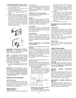
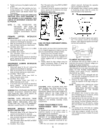
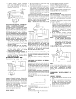
6. Tighten and secure the plastic bracket with screws. 7. To be totally sure that switches are functioning properly, see Primary, Secondary Interlock Switch and Monitor Switch Test Procedures. DO NOT ATTEMPT TO ADJUST INTERLOCK SWITCHES WITH OVEN ENERGIZED. IF THIS WARNING IS NOT OBSERVED, HIGH LEVELS OF MICROWAVE LEAKAGE MAY BE PRESENT. Test: Ohmmeter check from MSC to MSNC indicates short circuit. 3. If the switch does not operate as described above, replace all the switches and relay2. Repeat the above tests. COMPONENT TEST PROCEDURES cabinet removed, discharge the capacitor with an insulated screwdriver. 2. With alligator clips, connect a meter capable of measuring at least 120V AC, across the input terminals to the transformer. 120V AC NOTE: IF THE INTERLOCKS ARE REPLACED, THEY MUST BE ADJUSTED. SEE INTERLOCK ADJUSTMENTS SECTION FOR PROPER ADJUSTMENT PROCEDURE. PRIMARY (UPPER) INTERLOCK SWITCH TEST 1. Disconnect power to the unit. Remove the cabinet and discharge the capacitor. 2. With the ohmmeter set on the RX1 scale, take continuity readings as noted below. A) Condition: Door open Test: Ohmmeter check from LC to MSC indicates open circuit. B) Condition: Door closed Test: Ohmmeter check from LC to MSC indicates short circuit. 3. If the switch does not operate as described above, replace all the switches and relay2. Repeat the above tests. SECONDARY (LOWER) INTERLOCK SWITCH TEST 1. Disconnect power to the unit, remove the cabinet and discharge the capacitor. 2. With the ohmmeter set on the RX1 scale, take continuity readings as noted below. A) Condition: 1)Door open Test: Ohmmeter check from SISC to SISNO indicates open circuit. B) Condition: Door closed Test: Ohmmeter check from SISC to SISNO indicates short circuit. 3. If the switch does not operate as described above, replace all the switches and relay2. Repeat the above tests. WARNING:FOR CONTINUED PROTECTION AGAINST EXCESSIVE RADIATION EMISSION REPLACE ONLY WITH PARTS AS DESCRIBED IN THE PARTS LIST CAUTION: WHEN REPLACING THESE SWITCHES, USE ONLY FACTORY REPLACEMENT PARTS. REPLACING WITH ANY OTHER PART WILL VOID THE WARRANTY AND MAY CAUSE INJURY TO THE USER. MONITOR (MIDDLE) INTERLOCK SAFETY SWITCH TEST 1. Disconnect power to the unit. Remove the cabinet and discharge the capacitor. 2. With the ohmmeter set on the RX1 scale, take continuity readings as noted below. A) Condition: Door open Test: Ohmmeter check from MSC to MSNC indicates open circuit. B) Condition: Door closed HIGH VOLTAGE COMPONENT OPERATIONAL TEST In this section we have tried to lay these tests out in a logical sequence so that you can isolate any suspected high voltage problem. 1. Unplug oven from its power source. 2. After removing the cabinet discharge the capacitor by shorting the two capacitor terminals together with an insulated screwdriver. 3. Visually check the high voltage wiring for proper connections. Refer to wiring diagram for proper wiring sequence. CAUTIONS: HIGH VOLTAGES ARE PRESENT DURING THE COOK (HIGH) CYCLE, SO EXTREME CAUTION SHOULD BE OBSERVED. WHEN TESTS ARE COMPLETE, ALWAYS UNPLUG THE OVEN FROM ITS POWER SOURCE AND DISCHARGE THE CAPACITOR. NOTE: DO NOT TOUCH ANY OVEN COMPONENTS OR WIRING DURING OVEN OPERATION. POWER TRANSFORMER TESTS TRANSFORMER INPUT VOLTAGE CHECK An operational test can be made in order to determine whether or not primary power is being applied to the transformer. CAUTION: APPROXIMATELY 1840V AC IS PRESENT AT THE HIGH VOLTAGE TERMINAL OF POWER TRANSFORMER DURING COOK CYCLE. OBSERVE CAUTION AT ALL TIMES. 1. With the oven power cord unplugged and 5 3. Plug oven in and set for regular cook operation. If all primary circuits are functioning properly, 120V should be applied and measured across transformer. PRIMARY 1 FILAMENT WINDING (CATHODE) 2 F LOW VOLTAGE - 3.35V AC FA HIGH CURRENT FILAMENT VOLTAGE CHECK An operational test can be made in order to determine the amount of filament voltage produced by the power transformer. CAUTION: APPROXIMATELY 2070 VOLTS AC ARE PRESENT AT THE HIGH VOLTAGE TERMINAL OF THE POWER TRANSFORMER DURING COOK (HIGH CYCLE). OBSERVE CAUTION AT ALL TIMES. 1. With oven power cord unplugged and cab- inet removed, discharge the capacitor with an insulated screwdriver. 2. Remove the high voltage lead that connects the capacitor to the high voltage terminals. NOTE: DURING TEST OPERATION, KEEP METER, HANDS, ETC., WELL AWAY FROM THE HIGH VOLTAGE TERMINALS OF THE POWER TRANSFORMER. 3. With alligator clips, connect a meter capable of measuring up to 10 Volts AC across the magnetron filament terminals. 4. Apply power to the oven and put the oven into cook (high) cycle to get a filament voltage reading. A normal indication should be approximately 2.8 to 3.75 Volts AC. Unplug the oven before disconnecting the meter leads. 5. If a normal 2.8 to 3.75 Volts AC reading was indicated on the meter, go to step 6. 6. If the input voltage is normal, but no filament voltage is present, replace the power transformer.
-
 1
1 -
 2
2 -
 3
3 -
 4
4 -
 5
5 -
 6
6 -
 7
7 -
 8
8 -
 9
9 -
 10
10 -
 11
11 -
12
-
13
-
14
-
15
 |
 |