Sanyo Em-z2000s Service Manual - Page 21
magnetron - fuse replacement
 |
UPC - 086483045615
View all Sanyo Em-z2000s manuals
Add to My Manuals
Save this manual to your list of manuals |
Page 21 highlights
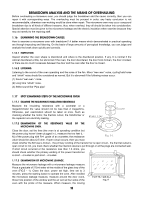
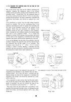
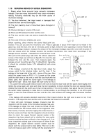
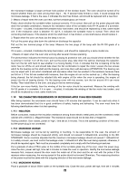
1.17.5 EXAMINE THE STARTING AND THE 8A FUSE OF THE MICROWAVE OVEN. Pull out the power plug, take off the cabinet, discharge the capacitor, measure the resistance value of the primary winding and the secondary winding of the transformer with an avometer (FIG.5 - 10 and FIG.5 - 9). The resistance value of the primary winding should be about 2.2 ohms, the secondary winding should be about 130 ohms. Otherwise, it indicates the transformer has broken, and should be replaced by a new one. If the transformer is normal, then the high voltage capacitor should be checked. Pull out the connecting plug of the capacitor, and measure it with R×1 grade of an avometer, the two rods of the avometer connect the two polarity of the capacitor. When they just connected, the reading of the avometer should be zero, then increases to nine megaohm slowly. Change the rod to different polarity, the reading repeat from zero to nine megaohm (FIG.5 - 11), it means the capacitor is normal. If the indicator of the avometer can't point out from zero to nine megaohms, it indicates the high voltage capacitor has broken, and should be replaced by a new one. If it is normal between the two pole of the capacitor, then the insulation between the capacitor pole and the cabinet should be measured with R×10K grade of an avometer. The resistance value should be "∞" (FIG.5 - 12). If it is short circuited or have a number reading, it indicates that the capacitor has been punctured or electricity leaked, and should be replaced by a same model, same capacity one. Fig.5-8 Fig.5-9 Fig.5-10 Fig.5-11 Fig.5-12 If the resistance value of the capacitor's two pole are "∞", the capacitor is normal. Then check the earth of the magnetron's two filaments to see whether they are short - circuited (FIG.5 - 13). If they are short - circuited and the filament strikes the shell of the magnetron, it indicates the magnetron magnetron has broken, and should be replaced by a new, same model one. If the magnetron is also normal, then test the pilot switch. Pull out the two plugs of the switch. Measure it with the R×1 grade of avometer, the two rod connect the plug of the switch, the resistance value should be "∞" (FIG.5 - 8). Then press down the pilot switch with a screwdriver, if the reading of the avometer pointed to zero, it indicates the pilot switch has broken, and should replace it with a new, same model one. 20
-
 1
1 -
2
-
3
-
4
-
5
-
6
-
7
-
8
-
9
-
10
-
11
-
12
-
13
-
14
-
15
-
 16
16 -
 17
17 -
 18
18 -
 19
19 -
 20
20 -
 21
21 -
 22
22 -
 23
23 -
 24
24 -
 25
25 -
 26
26
 |
 |
