Sanyo VCC-HD5400 VCC-HD5400 Manual - Page 12
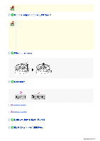
Outputting alarm signals ALARM OUT1-2, Inputting alarm signals ALARM IN1-4
 |
UPC - 086483075698
View all Sanyo VCC-HD5400 manuals
Add to My Manuals
Save this manual to your list of manuals |
Page 12 highlights
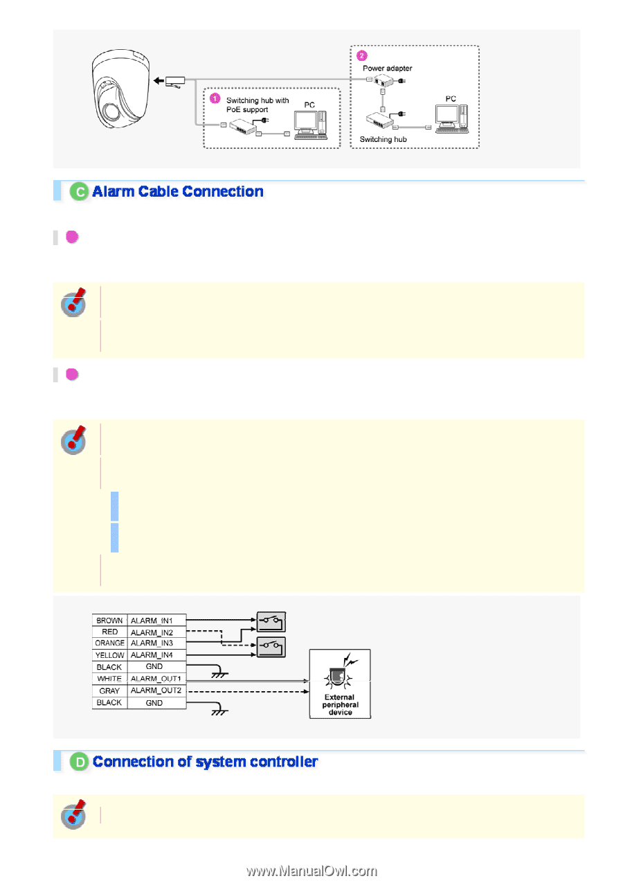
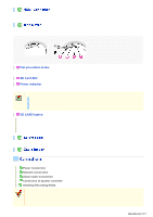
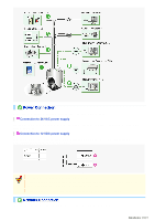
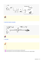
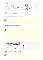
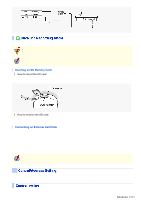
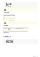
Use a thicker cable than 24AWG for connection. (Maximum length 600 m) 1 Outputting alarm signals (ALARM OUT1-2) Connect a buzzer, lamp, or other alarm device to the alarm output cable. Alarm can be output via two channels. After connecting an alarm device, configure the output conditions for the corresponding alarm output cable via network operation on the ALARM SETTINGS screen. Configuration of alarm output terminal is also possible via remote operation. For that, set [ALARM OUT] to "REMOTE" on the ALARM SETTINGS screen. 2 Inputting alarm signals (ALARM IN1-4) Connect an alarm switch, infrared sensor, or other device to detect alarm conditions to the alarm input cable. Up to four independent alarm input channels are available. After connecting an alarm device, configure the input conditions for the corresponding alarm input cable via network operation on the ALARM SETTINGS screen. To use the alarm input terminals as color/black-and-white mode switching terminals, follow the steps below. Under [DAY/NIGHT], set [DAY/NIGHT] to "COLOR" and select the cable you want to use in [EXT ALARM]. On the ALARM SETTINGS screen, in [POLARITY], select the signal polarity of the alarm input terminal. If you connect an external switch to ALARM IN1 terminal, you can specify time by controlling the switch. In this case, configure the [CLOCK IN] setting on CLOCK SETTINGS screen. By connecting a system controller (sold separately), the camera can be controlled remotely. Configure the protocol, baud rate and address. (Refer to "Control/Address Settings"). Introduction 12/15
-
 1
1 -
2
-
3
-
4
-
5
-
6
-
 7
7 -
 8
8 -
 9
9 -
 10
10 -
 11
11 -
 12
12 -
 13
13 -
 14
14 -
 15
15 -
 16
16 -
 17
17 -
18
-
19
-
20
-
21
-
22
-
23
-
24
-
25
-
26
-
27
-
28
-
29
-
30
-
31
-
32
-
33
-
34
-
35
-
36
-
37
-
38
-
39
-
40
-
41
-
42
-
43
-
44
-
45
-
46
-
47
-
48
-
49
-
50
-
51
-
52
-
53
-
54
-
55
-
56
-
57
-
58
-
59
-
60
-
61
-
62
-
63
-
64
-
65
-
66
-
67
-
68
-
69
-
70
-
71
-
72
-
73
-
74
-
75
-
76
-
77
-
78
-
79
-
80
-
81
-
82
-
83
-
84
-
85
-
86
-
87
-
88
-
89
-
90
-
91
-
92
-
93
-
94
-
95
-
96
-
97
-
98
-
99
-
100
-
101
-
102
-
103
-
104
-
105
-
106
-
107
-
108
-
109
-
110
-
111
-
112
-
113
-
114
-
115
-
116
-
117
-
118
-
119
-
120
-
121
-
122
-
123
-
124
-
125
-
126
-
127
-
128
-
129
-
130
-
131
-
132
-
133
-
134
-
135
-
136
-
137
-
138
-
139
-
140
-
141
-
142
-
143
-
144
-
145
 |
 |