Schwinn 103 Upright Bike Assembly Manual - Page 9
Assembly, Stage
 |
View all Schwinn 103 Upright Bike manuals
Add to My Manuals
Save this manual to your list of manuals |
Page 9 highlights
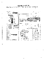
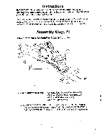
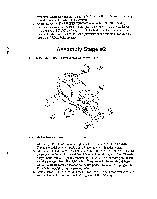
main unit. Make sure that the wheels on the front stabilizer tube are facing away from the main unit. Tighten bolts securely 2. Attach the REAR STABILIZER TUBE (#25) to the MAIN UNIT (#20) by inserting the two 90mm LONG BOLTS (#26) with the CURVED WASHERS (#17), and ACORN NUTS (#24) into the holes in the stabilizer and rear of the main unit. Make sure that the leveler adjustments on the rear stabilizer tube are facing up. Tighten bolts securely. Assembly Stage #2 Attach Pedals to the Crank Arms on Main Unit 28 0 20 6 23 Assembly hardware required: None 1. Attach right PEDAL (#23) to the right crank arm on the MAIN UNIT (#20). Thread the pedal onto the crank arm and then tighten with pedal wrench. 2. Attach left PEDAL (#23) to the left crank arm on the MAIN UNIT (#20). Thread the pedal onto the crank ann and then tighten with pedal wrench. Note; There is a right pedal and a left pedal, marked by R and L. The threading on the left pedal is reversed from the right pedal. Counterclockwiie rotation tightens while Clockwise rotation loosens on the left pedal. To avoid stripping of the threads be careful to use the proper pedal. 3. Attach PEDAL STRAPS,(#28) to each PEDAL (#23). Again each strap is labeled with an R or an L corresponding to the right and left pedal straps. 8
-
 1
1 -
2
-
3
-
 4
4 -
 5
5 -
 6
6 -
 7
7 -
 8
8 -
 9
9 -
 10
10 -
 11
11 -
 12
12 -
 13
13 -
 14
14 -
15
 |
 |
