Schwinn 201 Recumbent Bike Assembly Manual - Page 13
protruding
 |
View all Schwinn 201 Recumbent Bike manuals
Add to My Manuals
Save this manual to your list of manuals |
Page 13 highlights
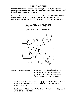
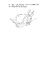
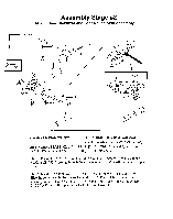
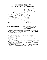
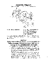
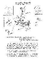
into main unit. CAUTION! If the wire is protruding from the bottom of the seat rail it may be severed or damaged when the seat rail is fully inserted into the main unit! This may result in a non-functioning handgrip heart rate. Carefully slide the seat rail until the slots in the side of the rail line up with the holes in the main unit. Step 11: Attach SEAT RAIL (#9) to MAIN UNIT (#31) with 4, 16 mm BOLTS (#22) and 4 FLAT WASHERS (#7). Again do not tighten until after step 12. Place BOLT COVERS (23) over BOLTS (#22) in MAIN UNIT (#31). Step 12: Attach REAR STABILIZER TUBE (#10) to BASE FRAME (#32) with 2 90mm LONG BOLTS (#24), 2 CURVED WASHERS (#19), and 2 ACORN NUTS (#20). Tighten with provided wrench. Tighten Allen bolts from steps 10 and 11 with provided Allen wrench. Step 12b: Feed the excess coiled wire from the back end of the seat rail through the hole on top of the seat rail until about 6 inches of coiled wire is on the outside of the seat rail. Attach the end of the wire to the back of the handlebar assembly. Feed the remaining excess wire into the seat rail and replace the end cap on the end of the seat rail. After completing assembly stage 5 verify that the handgrip heart rate works by hitting manual start and then placing your hand on the grip heart pad located on the handlebars. Verify that a heart rate registers on the computer panel after several seconds.
-
 1
1 -
2
-
3
-
4
-
5
-
6
-
7
-
 8
8 -
 9
9 -
 10
10 -
 11
11 -
 12
12 -
 13
13 -
 14
14 -
 15
15 -
 16
16
 |
 |
