Seagate ST15150N Product Manual - Page 65
Synchronized spindles interface
 |
View all Seagate ST15150N manuals
Add to My Manuals
Save this manual to your list of manuals |
Page 65 highlights
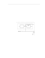
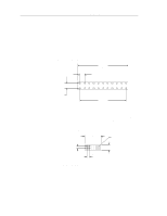
ST15150N/ND/W/WD/WC/DC Product Manual, Rev. D 55 10.2 Synchronized spindles interface The synchronized spindles interface (SSI) allows several drives operating from the same host to operate their spindles at a synchronized rotational rate. The system operation is described in Section 5.7. 10.2.1 Electrical description The electrical interface consists of one digital TTL reference index signal and ground. The reference index signal (SSREF+) is an output if the drive is configured as a master and is an input otherwise. The reference index signal is connected from drive to drive in a daisy-chain fashion as shown in Figure 4. 10.2.1.1 Drivers and receivers Figure 25 shows a diagram of the driver/receiver circuit. The driver circuits have the following electrical specifications: Negated (false) 0.V to +0.4V @ I = -24 mA (max) Asserted (true) +2.24V to +5.25V @ I = +250 µA Main PWA Open Collector Driver Receiver 2.21K Ohm +5V SSREF + GND J4 - 1 (N/ND Drives) J5 - 11 (W/WD Drives) J4 - 2 (N/ND Drives) J5 - 12 (W/WD Drives) ST15150WC/DC drives use J04 pin 6 for synchronizing spindles. Figure 25. SCSI reference index signal driver/receiver combination
-
 1
1 -
2
-
3
-
4
-
5
-
6
-
7
-
8
-
9
-
10
-
11
-
12
-
13
-
14
-
15
-
16
-
17
-
18
-
19
-
20
-
21
-
22
-
23
-
24
-
25
-
26
-
27
-
28
-
29
-
30
-
31
-
32
-
33
-
34
-
35
-
36
-
37
-
38
-
39
-
40
-
41
-
42
-
43
-
44
-
45
-
46
-
47
-
48
-
49
-
50
-
51
-
52
-
53
-
54
-
55
-
56
-
57
-
58
-
59
-
 60
60 -
 61
61 -
 62
62 -
 63
63 -
 64
64 -
 65
65 -
 66
66 -
 67
67 -
 68
68 -
 69
69 -
 70
70 -
71
-
72
-
73
-
74
-
75
-
76
-
77
-
78
-
79
-
80
-
81
-
82
-
83
-
84
-
85
-
86
-
87
-
88
-
89
-
90
-
91
-
92
-
93
-
94
-
95
-
96
-
97
-
98
-
99
-
100
-
101
-
102
 |
 |
