Seagate ST200FM0002 Pulsar.2 SAS Product Manual - Page 22
Seagate ST200FM0002 Manual
 |
View all Seagate ST200FM0002 manuals
Add to My Manuals
Save this manual to your list of manuals |
Page 22 highlights
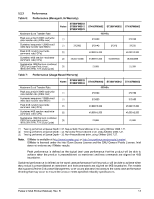
Due to the nature of Flash memory technologies there are many factors that can result in values different than those stated in this specification. Some discrepancies can be caused by bandwidth limitations in the host adapter, operating system, or driver limitations. It is not the intent of this manual to cover all possible causes of performance discrepancies. When evaluating performance of SSD devices, it is recommended to measure performance of the device in a method that resembles the targeted application using real world data and workloads. Test time should also be adequately large to ensure that sustainable metrics and measures are obtained. 5.3 Start/stop time The drive accepts the commands listed in the SAS Interface Manual less than 3 seconds after DC power has been applied. If the drive receives a NOTIFY (ENABLE SPINUP) primitive through either port and has not received a START STOP UNIT command with the START bit equal to 0, the drive becomes ready for normal operations within 15 seconds (excluding the error recovery procedure). If the drive receives a START STOP UNIT command with the START bit equal to 0 before receiving a NOTIFY (ENABLE SPINUP) primitive, the drive waits for a START STOP UNIT command with the START bit equal to 1. After receiving a START STOP UNIT command with the START bit equal to 1, the drive waits for a NOTIFY (ENABLE SPINUP) primitive. After receiving a NOTIFY (ENABLE SPINUP) primitive through either port, the drive becomes ready for normal operations within 15 seconds (excluding the error recovery procedure). If the drive receives a START STOP UNIT command with the START bit and IMMED bit equal to 1 and does not receive a NOTIFY (ENABLE SPINUP) primitive within 5 seconds, the drive fails the START STOP UNIT command. The START STOP UNIT command may be used to command the drive to stop. Stop time is 3 seconds (maximum) from removal of DC power. SCSI stop time is 3 seconds. There is no power control switch on the drive. 5.4 Cache control All default cache mode parameter values (Mode Page 08h) for standard OEM versions of this drive family are given in Table 20 and 21. 5.4.1 Caching write data Write caching is a write operation by the drive that makes use of a drive buffer storage area where the data to be written to the medium is stored while the drive performs the WRITE command. If the number of write data logical blocks exceed the size of the segment being written into, when the end of the segment is reached, the data is written into the beginning of the same cache segment, overwriting the data that was written there at the beginning of the operation; however, the drive does not overwrite data that has not yet been written to the medium. If write caching is enabled (WCE=1), then the drive may return Good status on a WRITE command after the data has been transferred into the cache, but before the data has been written to the medium. If an error occurs while writing the data to the medium, and Good status has already been returned, a deferred error will be generated. Data that has not been written to the medium is protected by a back up power source which provides the ability of the data to be written to non-volatile medium in the event of an unexpected power loss. The SYNCHRONIZE CACHE command may be used to force the drive to write all cached write data to the medium. Upon completion of a SYNCHRONIZE CACHE command, all data received from previous WRITE commands will have been written to the medium. Tables 19, 20 and 21 show the mode default settings for the drive. 14 Pulsar.2 SAS Product Manual, Rev. B
-
 1
1 -
2
-
3
-
4
-
5
-
6
-
7
-
8
-
9
-
10
-
11
-
12
-
13
-
14
-
15
-
16
-
 17
17 -
 18
18 -
 19
19 -
 20
20 -
 21
21 -
 22
22 -
 23
23 -
 24
24 -
 25
25 -
 26
26 -
 27
27 -
28
-
29
-
30
-
31
-
32
-
33
-
34
-
35
-
36
-
37
-
38
-
39
-
40
-
41
-
42
-
43
-
44
-
45
-
46
-
47
-
48
-
49
-
50
-
51
-
52
-
53
-
54
-
55
-
56
-
57
-
58
-
59
-
60
-
61
-
62
-
63
-
64
-
65
-
66
-
67
-
68
-
69
-
70
-
71
-
72
-
73
-
74
-
75
-
76
-
77
-
78
-
79
-
80
-
81
-
82
 |
 |