Seagate ST200FM0002 Pulsar.2 SAS Product Manual - Page 27
Seagate ST200FM0002 Manual
 |
View all Seagate ST200FM0002 manuals
Add to My Manuals
Save this manual to your list of manuals |
Page 27 highlights
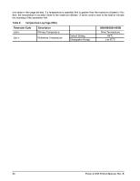
Determining rate S.M.A.R.T. monitors the rate at which errors occur and signals a predictive failure if the rate of degraded errors increases to an unacceptable level. To determine rate, error events are logged and compared to the number of total operations for a given attribute. The interval defines the number of operations over which to measure the rate. The counter that keeps track of the current number of operations is referred to as the Interval Counter. S.M.A.R.T. measures error rates. All errors for each monitored attribute are recorded. A counter keeps track of the number of errors for the current interval. This counter is referred to as the Failure Counter. Error rate is the number of errors per operation. The algorithm that S.M.A.R.T. uses to record rates of error is to set thresholds for the number of errors and appropriate interval. If the number of errors exceeds the threshold before the interval expires, the error rate is considered to be unacceptable. If the number of errors does not exceed the threshold before the interval expires, the error rate is considered to be acceptable. In either case, the interval and failure counters are reset and the process starts over. Predictive failures S.M.A.R.T. signals predictive failures when the drive is performing unacceptably for a period of time. The firmware keeps a running count of the number of times the error rate for each attribute is unacceptable. To accomplish this, a counter is incremented each time the error rate is unacceptable and decremented (not to exceed zero) whenever the error rate is acceptable. If the counter continually increments such that it reaches the predictive threshold, a predictive failure is signaled. This counter is referred to as the Failure History Counter. There is a separate Failure History Counter for each attribute. 6.3.5 Thermal monitor Pulsar.2 drives implement a temperature warning system which: 1. Signals the host if the temperature exceeds a value which would threaten the drive. 2. Signals the host if the temperature exceeds a user-specified value. (i.e., the reference temperature value) 3. Saves a S.M.A.R.T. data frame on the drive which exceeds the threatening temperature value. A temperature sensor monitors the drive temperature and issues a warning over the interface when the temperature exceeds a set threshold. The temperature is measured at power-up and then at ten-minute intervals after power-up. The thermal monitor system generates a warning code of 01-0B01 when the temperature exceeds the specified limit in compliance with the SCSI standard. The drive temperature is reported in the FRU code field of MODE SENSE data. Administrators can use this information to determine if the warning is due to the temperature exceeding the drive threatening temperature or the user-specified temperature. This feature is controlled by the Enable Warning (EWasc) bit, and the reporting mechanism is controlled by the Method of Reporting Informational Exceptions field (MRIE) on the Informational Exceptions Control (IEC) mode page (1Ch). The current algorithm implements two temperature trip points. The first trip point is set at the maximum temperature limit according to the drive specification. The second trip point is user-selectable using the LOG SELECT command. The reference temperature parameter in the temperature log page (see Table 8) can be used to set this trip point. The default value for this drive is listed in the table, however, applications can set it to Pulsar.2 SAS Product Manual, Rev. B 19
-
 1
1 -
2
-
3
-
4
-
5
-
6
-
7
-
8
-
9
-
10
-
11
-
12
-
13
-
14
-
15
-
16
-
17
-
18
-
19
-
20
-
21
-
 22
22 -
 23
23 -
 24
24 -
 25
25 -
 26
26 -
 27
27 -
 28
28 -
 29
29 -
 30
30 -
 31
31 -
 32
32 -
33
-
34
-
35
-
36
-
37
-
38
-
39
-
40
-
41
-
42
-
43
-
44
-
45
-
46
-
47
-
48
-
49
-
50
-
51
-
52
-
53
-
54
-
55
-
56
-
57
-
58
-
59
-
60
-
61
-
62
-
63
-
64
-
65
-
66
-
67
-
68
-
69
-
70
-
71
-
72
-
73
-
74
-
75
-
76
-
77
-
78
-
79
-
80
-
81
-
82
 |
 |