Seagate ST320005N4A1AS Barracuda 7200.10 SATA Product Manual - Page 52
Serial ATA device plug connector pin definitions
 |
View all Seagate ST320005N4A1AS manuals
Add to My Manuals
Save this manual to your list of manuals |
Page 52 highlights
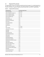
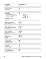
4.2 Serial ATA device plug connector pin definitions Table 15 summarizes the signals on the Serial ATA interface and power connectors.. Table 15: Serial ATA connector pin definitions Segment Pin S1 S2 S3 S4 S5 S6 Signal S7 Function Ground A+ AGround BB+ Ground Definition 2nd mate Differential signal pair A from Phy 2nd mate Differential signal pair B from Phy 2nd mate Key and spacing separate signal and power segments P1 V33 P2 V33 P3 V33 P4 Ground 3.3V power 3.3V power 3.3V power, pre-charge, 2nd mate 1st mate P5 Ground 2nd mate P6 Ground 2nd mate P7 V5 Power P8 V5 P9 V5 P10 Ground 5V power, pre-charge, 2nd mate 5V power 5V power 2nd mate P11 Ground or LED signal If grounded, drive does not use deferred spin P12 Ground 1st mate. P13 V12 P14 V12 P15 V12 12V power, pre-charge, 2nd mate 12V power 12V power Notes: 1. All pins are in a single row, with a 1.27 mm (0.050") pitch. 2. The comments on the mating sequence apply to the case of backplane blindmate connector only. In this case, the mating sequences are: • the ground pins P4 and P12. • the pre-charge power pins and the other ground pins. • the signal pins and the rest of the power pins. 3. There are three power pins for each voltage. One pin from each voltage is used for pre-charge when installed in a blind-mate backplane configuration. 4. All used voltage pins (Vx) must be terminated. 46 Barracuda 7200.10 Serial ATA Product Manual, Rev. K
-
 1
1 -
2
-
3
-
4
-
5
-
6
-
7
-
8
-
9
-
10
-
11
-
12
-
13
-
14
-
15
-
16
-
17
-
18
-
19
-
20
-
21
-
22
-
23
-
24
-
25
-
26
-
27
-
28
-
29
-
30
-
31
-
32
-
33
-
34
-
35
-
36
-
37
-
38
-
39
-
40
-
41
-
42
-
43
-
44
-
45
-
46
-
 47
47 -
 48
48 -
 49
49 -
 50
50 -
 51
51 -
 52
52 -
 53
53 -
 54
54 -
 55
55 -
 56
56 -
 57
57 -
58
-
59
-
60
-
61
-
62
-
63
-
64
-
65
-
66
-
67
-
68
 |
 |