Seagate ST336607LC ST3146807LC Model Product Manual PDF - Page 70
Cheetah 10K.6 SCSI Product Manual, Rev. D, 6.4.2, Mating connectors for LC model drives
 |
UPC - 740617072488
View all Seagate ST336607LC manuals
Add to My Manuals
Save this manual to your list of manuals |
Page 70 highlights
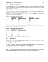
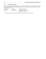
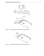
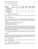
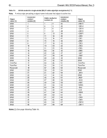
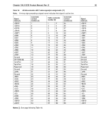
60 Cheetah 10K.6 SCSI Product Manual, Rev. D Recommended mating flat cable connector part numbers are: Amp Model 786096-7 Female, 68-pin, panel mount Amp Model 786090-7 Female, 68-pin, cable mount Amp Model 749925-5 (50 mil conductor centers, 28 or 30 AWG wire) Use two, 34 conductor, 50 mil center flat cable with this connector. This type connector can only be used on cable ends. [1] Amp Model 88-5870-294-5 W/O Strain Relief (25 mil conductor centers, 30 AWG wire). Use either on cable ends or in cable middle section for daisy-chain installations [1]. Amp Model 1-480420-0 Power connector 4 circuit housing Berg 69307-012 12-position, 2 x 6, 2 mm receptacle housing [1] See Figure 24. The drive device connector is a nonshielded 68-conductor connector consisting of two rows of 34 female pins with adjacent pins 50 mils apart. The connector is keyed by means of its shape (see Figure 25). 9.6.4.2 Mating connectors for LC model drives The nonshielded connector shall be an 80-conductor connector consisting of two rows of 40 contacts with adjacent contacts 50 (1.27 mm) mils apart (see Figure 26). I/O connection using a cable is not recommended. The length and size of the host equipment DC power carrying conductors from the DC power source to the host equipment 80-pin disc drive interface connector(s) should be strictly designed according to proper power transmission design concepts. No possibility for the equipment user to attach an 80-pin cable/connector should be allowed, since the length of the DC power carrying conductors could not be controlled and therefore could become too long for safe power transmission to the drive. Daisy-chain 80-conductor cables should especially not be allowed, since the power-carrying conductors on the 80-conductor interface were not intended to support a series of drives. To insure that both drive connector and host equipment mating connector mate properly, both drive connector and host equipment mating connector must meet the provisions of "SFF-8451 Specification for SCA-2 Unshielded Connections." To obtain this specification, visit the following web site: www.sffcommittee.org
-
 1
1 -
2
-
3
-
4
-
5
-
6
-
7
-
8
-
9
-
10
-
11
-
12
-
13
-
14
-
15
-
16
-
17
-
18
-
19
-
20
-
21
-
22
-
23
-
24
-
25
-
26
-
27
-
28
-
29
-
30
-
31
-
32
-
33
-
34
-
35
-
36
-
37
-
38
-
39
-
40
-
41
-
42
-
43
-
44
-
45
-
46
-
47
-
48
-
49
-
50
-
51
-
52
-
53
-
54
-
55
-
56
-
57
-
58
-
59
-
60
-
61
-
62
-
63
-
64
-
 65
65 -
 66
66 -
 67
67 -
 68
68 -
 69
69 -
 70
70 -
 71
71 -
 72
72 -
 73
73 -
 74
74 -
 75
75 -
76
-
77
-
78
-
79
-
80
-
81
-
82
-
83
-
84
-
85
-
86
-
87
-
88
-
89
-
90
-
91
-
92
-
93
-
94
-
95
-
96
 |
 |
