Seagate ST336607LC ST3146807LC Model Product Manual PDF - Page 79
Cheetah 10K.6 SCSI Product Manual, Rev. D, LVD input characteristics, 7.1.1, General cable
 |
UPC - 740617072488
View all Seagate ST336607LC manuals
Add to My Manuals
Save this manual to your list of manuals |
Page 79 highlights
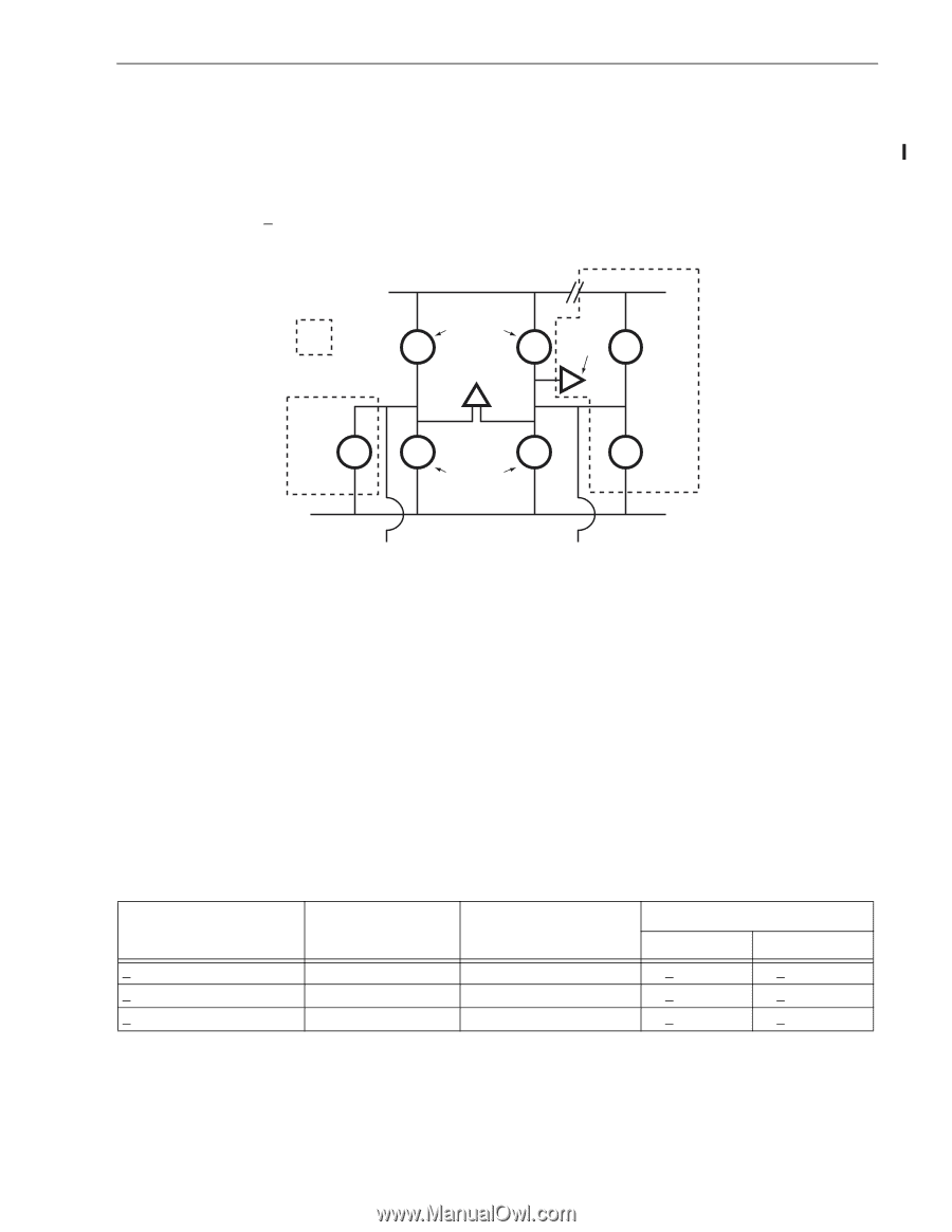
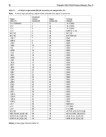
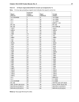
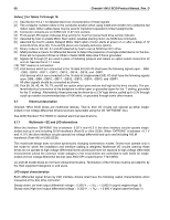
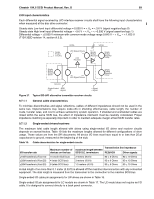
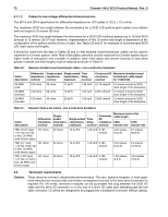
Cheetah 10K.6 SCSI Product Manual, Rev. D 69 LVD input characteristics Each differential signal received by LVD interface receiver circuits shall have the following input characteristics when measured at the disc drive connector: Steady state Low level input differential voltage = 0.030 V = < Vin = < 3.6 V (signal negation/logic 0) Steady state High level input differential voltage = -3.6 V = < Vin = < -0.030 V (signal assertion/logic 1) Differential voltage = +0.030 V minimum with common-mode voltage range 0.845 V = < Vcm = < 1.655 V. (T10/1302D revision 14, section A.3.2). Single Ended Circuitry VCCA LVD Signal Drivers LVD Receiver VCCB Single Ended Receiver Single Ended Negation Driver Single Ended Ground Driver LVD Signal Drivers Single Ended Assertion Driver Ground Single Ended: GND LVD: +Signal -Signal -Signal Figure 27. Typical SE-LVD alternative transmitter receiver circuits 9.7.1.1 General cable characteristics To minimize discontinuities and signal reflections, cables of different impedances should not be used in the same bus. Implementations may require trade-offs in shielding effectiveness, cable length, the number of loads, transfer rates, and cost to achieve satisfactory system operation. If shielded and unshielded cables are mixed within the same SCSI bus, the effect of impedance mismatch must be carefully considered. Proper impedance matching is especially important in order to maintain adequate margin at fast SCSI transfer rates. 9.7.1.2 Single-ended drivers/receivers The maximum total cable length allowed with drives using single-ended I/O driver and receiver circuits depends on several factors. Table 19 lists the maximum lengths allowed for different configurations of drive usage. These values are from the SPI documents. All device I/O lines must have equal to or less than 25 pf capacitance to ground, measured at the beginning of the stub. Table 19: Cable characteristics for single-ended circuits I/O transfer rate
-
 1
1 -
2
-
3
-
4
-
5
-
6
-
7
-
8
-
9
-
10
-
11
-
12
-
13
-
14
-
15
-
16
-
17
-
18
-
19
-
20
-
21
-
22
-
23
-
24
-
25
-
26
-
27
-
28
-
29
-
30
-
31
-
32
-
33
-
34
-
35
-
36
-
37
-
38
-
39
-
40
-
41
-
42
-
43
-
44
-
45
-
46
-
47
-
48
-
49
-
50
-
51
-
52
-
53
-
54
-
55
-
56
-
57
-
58
-
59
-
60
-
61
-
62
-
63
-
64
-
65
-
66
-
67
-
68
-
69
-
70
-
71
-
72
-
73
-
 74
74 -
 75
75 -
 76
76 -
 77
77 -
 78
78 -
 79
79 -
 80
80 -
 81
81 -
 82
82 -
 83
83 -
 84
84 -
85
-
86
-
87
-
88
-
89
-
90
-
91
-
92
-
93
-
94
-
95
-
96
 |
 |