Seagate ST373207FC Cheetah 10K.7 FC Product Manual - Page 87
Signal characteristics
 |
UPC - 000056439373
View all Seagate ST373207FC manuals
Add to My Manuals
Save this manual to your list of manuals |
Page 87 highlights
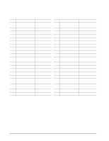
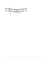
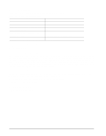
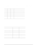
9.5.12 Device control codes The drive inputs a Device Control Code on the DEV_CTRL_CODE lines at power up to determine the link rate on the Fibre Channel ports. Both ports run at the same rate. If the backpanel does not connect to these lines, the drive has 10K ohm pull up resistors that default the device control code to 7 (1.0625 GHz). Table 36 lists the supported codes. Table 36: Device control code values 2 (pin 17) 1 (pin 18) 0 (pin 39) Definition 0 0 0 Reserved for Power failure warning. 0 0 1 Reserved for auto negotiation of link rate. 0 1 0 Reserved. 0 1 1 Reserved. 1 0 0 Reserved. 1 0 1 Reserved. 1 1 0 2.125 GHz operation on both ports. 1 1 1 1.0625 GHz operation on both ports. 9.6 Signal characteristics This section describes the electrical signal characteristics of the drive's input and output signals. See Table 32 on page 70 for signal type and signal name information. 9.6.1 TTL input characteristics Table 37 provides the TTL characteristics. Table 37: TTL characteristics State Input high Input low Output high (-EN Bypass A, B) Output low (-EN Bypass A, B) Output high (-Parallel ESI) Output low (-Parallel ESI) Output high (all other outputs) Output low (all other outputs) Voltage 1.9 < VIH < 5.5V -0.5V < VIL < 0.9V 2.4 < VOH < 5.25V VOL < 0.5V 2.4 < VOH < 0.9 VCC VOH > 0.9VCC 0 < VOL < .45V 2.4 < VOH < 0.9 VCC VOH > 0.9VCC 0 < VOL < .45V Current IIH = ±500nA max. IOL = ±500nA max. IOH < -3mA IOL < 3mA IOH < -2.4mA IOH < -500µA IOL < 2.4mA IOH < -1.6mA IOH < -500µA IOL < 1.6mA Cheetah 10K.7 FC Product Manual, Rev. D 75
-
 1
1 -
2
-
3
-
4
-
5
-
6
-
7
-
8
-
9
-
10
-
11
-
12
-
13
-
14
-
15
-
16
-
17
-
18
-
19
-
20
-
21
-
22
-
23
-
24
-
25
-
26
-
27
-
28
-
29
-
30
-
31
-
32
-
33
-
34
-
35
-
36
-
37
-
38
-
39
-
40
-
41
-
42
-
43
-
44
-
45
-
46
-
47
-
48
-
49
-
50
-
51
-
52
-
53
-
54
-
55
-
56
-
57
-
58
-
59
-
60
-
61
-
62
-
63
-
64
-
65
-
66
-
67
-
68
-
69
-
70
-
71
-
72
-
73
-
74
-
75
-
76
-
77
-
78
-
79
-
80
-
81
-
 82
82 -
 83
83 -
 84
84 -
 85
85 -
 86
86 -
 87
87 -
 88
88 -
 89
89 -
 90
90 -
 91
91 -
 92
92 -
93
-
94
-
95
-
96
-
97
-
98
-
99
-
100
-
101
-
102
-
103
-
104
-
105
-
106
 |
 |
