Seagate ST373207LC Cheetah 10K.7 SCSI Product Manual - Page 36
Notes, SE mode, LVD mode
 |
UPC - 000056373851
View all Seagate ST373207LC manuals
Add to My Manuals
Save this manual to your list of manuals |
Page 36 highlights
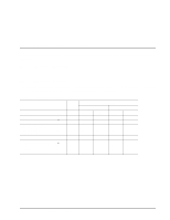
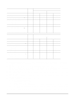
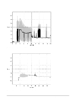
Voltage Regulation Average idle current DC X Maximum starting current (peak DC) DC 3σ (peak AC) AC 3σ Delayed motor start (max) DC 3σ Peak operating current DC X Maximum DC 3σ Maximum (peak) DC 3σ Notes [5] [1][7] [3] [3] [1] [4] [1] [6] [1] ST3146707 SE mode LVD mode +5 V ±5% 0.54 +12 V ±5% [2] 0.42 +5 V ±5% 0.54 +12 V ±5% [2] 0.42 0.77 1.89 1.09 3.66 0.54 0.06 0.76 1.89 1.06 3.83 0.54 0.06 0.60 0.81 0.62 0.83 1.52 2.50 0.61 0.83 0.63 0.85 1.44 2.48 Voltage Regulation Average idle current DC X Maximum starting current (peak DC) DC 3σ (peak AC) AC 3σ Delayed motor start (max) DC 3σ Peak operating current DC X Maximum DC 3σ Maximum (peak) DC 3σ Notes [5] [1][7] [3] [3] [1] [4] [1] [6] [1] ST373207 SE mode LVD mode +5 V ±5% 0.54 +12 V ±5% [2] 0.34 +5 V ±5% 0.54 +12 V ±5% [2] 0.34 0.76 1.55 1.08 3.04 0.54 0.06 0.77 1.56 1.03 3.36 0.54 0.06 0.62 0.73 0.63 0.76 1.56 2.46 0.60 0.72 0.61 0.74 1.48 2.40 [1] Measured with average reading DC ammeter or equivalent sampling scope. Instantaneous current peaks will exceed these values. Power supply at nominal voltage. Number of drives tested = 6, 35 Degrees C ambient. [2] For +12 V, a -10% tolerance is permissible during initial start of spindle, and must return to ±5% before 10,000 rpm is reached. The ±5% must be maintained after the drive signifies that its power-up sequence has been completed and that the drive is able to accept selection by the host initiator. [3] See +12 V current profile in Figure 2. [4] This condition occurs when the Motor Start Option is enabled and the drive has not yet received a Start Motor command. [5] See Section 6.2.1 "Conducted Noise Immunity." Specified voltage tolerance is inclusive of ripple, noise, and transient response. [6] Operating condition is defined as random 8 block reads at: 257 I/Os per second (ST3300007) LVD 257 I/Os per second (ST3146707) LVD 256 I/Os per second (ST373207) LVD Current and power specified at nominal voltages. Decreasing +5 volts by 5% increases 5 volt current by
-
 1
1 -
2
-
3
-
4
-
5
-
6
-
7
-
8
-
9
-
10
-
11
-
12
-
13
-
14
-
15
-
16
-
17
-
18
-
19
-
20
-
21
-
22
-
23
-
24
-
25
-
26
-
27
-
28
-
29
-
30
-
 31
31 -
 32
32 -
 33
33 -
 34
34 -
 35
35 -
 36
36 -
 37
37 -
 38
38 -
 39
39 -
 40
40 -
 41
41 -
42
-
43
-
44
-
45
-
46
-
47
-
48
-
49
-
50
-
51
-
52
-
53
-
54
-
55
-
56
-
57
-
58
-
59
-
60
-
61
-
62
-
63
-
64
-
65
-
66
-
67
-
68
-
69
-
70
-
71
-
72
-
73
-
74
-
75
-
76
-
77
-
78
-
79
-
80
-
81
-
82
-
83
-
84
-
85
-
86
-
87
-
88
-
89
-
90
-
91
-
92
-
93
-
94
-
95
-
96
-
97
-
98
-
99
-
100
-
101
-
102
-
103
-
104
-
105
-
106
-
107
-
108
-
109
-
110
 |
 |
