Seagate ST373207LC Cheetah 10K.7 SCSI Product Manual - Page 37
General Notes from Table 2
 |
UPC - 000056373851
View all Seagate ST373207LC manuals
Add to My Manuals
Save this manual to your list of manuals |
Page 37 highlights
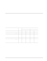
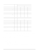
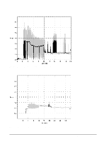
three-quarters to maximum track. General Notes from Table 2: 1. Minimum current loading for each supply voltage is not less than 1.2% of the maximum operating current shown. 2. The +5 and +12 volt supplies shall employ separate ground returns. 3. Where power is provided to multiple drives from a common supply, careful consideration for individual drive power requirements should be noted. Where multiple units are powered on simultaneously, the peak starting current must be available to each device. 4. Parameters, other than spindle start, are measured after a 10-minute warm up. 5. No terminator power. 6.2.1 Conducted noise immunity Noise is specified as a periodic and random distribution of frequencies covering a band from DC to 20 MHz. Maximum allowed noise values given below are peak to peak measurements and apply at the drive power connector. +5 V = +12 V = 250 mV pp from 100 Hz to 20 MHz. 800 mV pp from 100 Hz to 8 KHz. 450 mV pp from 8 KHz to 20 KHz. 250 mV pp from 20 KHz to 5 MHz. 6.2.2 Power sequencing The drive does not require power sequencing. The drive protects against inadvertent writing during power-up and down. Daisy-chain operation requires that power be supplied to the SCSI bus terminator to ensure proper termination of the peripheral I/O cables. To automatically delay motor start based on the target ID (SCSI ID) enable the Delay Motor Start option and disable the Enable Motor Start option on the J2 connector on LW models or on the backplane for LC models. See Section 8.1 for pin selection information. To delay the motor until the drive receives a Start Unit command, enable the Enable Remote Motor Start option on the J2 connector on LW models or on the backplane for LC models. 6.2.3 12 V - Current profile Figure 2, 4 and 6 identify the drive +12 V current profiles and figures 3, 5 and 7 identify the drive +5 V current profiles. The current during the various times is as shown: T0 - Power is applied to the drive. T1 - Controller self tests are performed. T2 - Spindle begins to accelerate under current limiting after performing drive internal diagnostics. See Note 1 of Table 2. T3 - The spindle is up to speed and the head-arm restraint is unlocked. T4 - The adaptive servo calibration sequence is performed. T5 - Calibration is complete and drive is ready for reading and writing. Note. All times and currents are typical. See Table 2 for maximum current requirements. Cheetah 10K.7 SCSI Product Manual, Rev. D 27
-
 1
1 -
2
-
3
-
4
-
5
-
6
-
7
-
8
-
9
-
10
-
11
-
12
-
13
-
14
-
15
-
16
-
17
-
18
-
19
-
20
-
21
-
22
-
23
-
24
-
25
-
26
-
27
-
28
-
29
-
30
-
31
-
 32
32 -
 33
33 -
 34
34 -
 35
35 -
 36
36 -
 37
37 -
 38
38 -
 39
39 -
 40
40 -
 41
41 -
 42
42 -
43
-
44
-
45
-
46
-
47
-
48
-
49
-
50
-
51
-
52
-
53
-
54
-
55
-
56
-
57
-
58
-
59
-
60
-
61
-
62
-
63
-
64
-
65
-
66
-
67
-
68
-
69
-
70
-
71
-
72
-
73
-
74
-
75
-
76
-
77
-
78
-
79
-
80
-
81
-
82
-
83
-
84
-
85
-
86
-
87
-
88
-
89
-
90
-
91
-
92
-
93
-
94
-
95
-
96
-
97
-
98
-
99
-
100
-
101
-
102
-
103
-
104
-
105
-
106
-
107
-
108
-
109
-
110
 |
 |
