Seagate ST9500325AS Momentus 5400.6 SATA Product Manual - Page 29
Drive mounting - dimensions mm
 |
UPC - 890552607471
View all Seagate ST9500325AS manuals
Add to My Manuals
Save this manual to your list of manuals |
Page 29 highlights
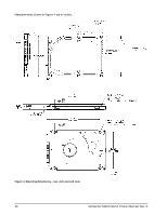
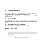
3.4 Drive mounting You can mount the drive using four screws in the side-mounting holes or four screws in the bottom-mounting holes. See Figure 4 for drive mounting dimensions. Follow these important mounting precautions when mounting the drive: • Allow a minimum clearance of 0.030 inches (0.76 mm) around the entire perimeter of the drive for cooling. • Use only M3 UNC mounting screws. • Do not overtighten the mounting screws. Maximum torque: 4.0 inch-lb (0.4519 N-m). • Four (4) threads (0.080 inches, 2.032 mm) minimum screw engagement recommended. • Avoid excessive drive distortion when mounting. Refer to the following specifications for stiffness/deflection information: Top cover stiffness/deflection Operating with no performance degradation, emitted noise, mechanical damage, or hard errors Non-operating with no hard errors 10 mm probe: 2.0kgf OR 5 mm probe: 0.92kgf 20 mm probe: 2kgf at any point of top cover 20 mm probe: 15kgf at top cover edges only Momentus 5400.6 SATA Product Manual, Rev. E 23
-
 1
1 -
2
-
3
-
4
-
5
-
6
-
7
-
8
-
9
-
10
-
11
-
12
-
13
-
14
-
15
-
16
-
17
-
18
-
19
-
20
-
21
-
22
-
23
-
 24
24 -
 25
25 -
 26
26 -
 27
27 -
 28
28 -
 29
29 -
 30
30 -
 31
31 -
 32
32 -
 33
33 -
 34
34 -
35
-
36
-
37
-
38
-
39
-
40
-
41
-
42
-
43
-
44
-
45
-
46
-
47
-
48
 |
 |
