Sealey SC10 Instruction Manual - Page 2

fig.2, fig.1

Page 2 highlights

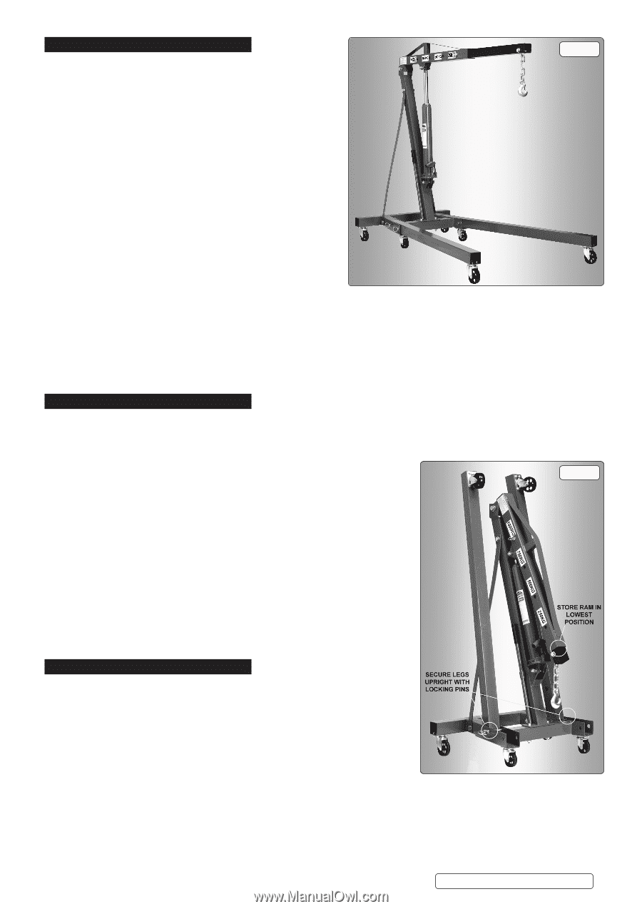
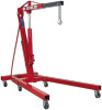
3. SPECIFICATION fig.1 TECHNICAL DATA Rated Capacity Safe Working Load (SWL) 1t (tested to 50% overload). Height jib down 1390mm Height legs folded 1440mm Height of frame 185mm Length legs extended 1620mm Length of jib position 1 830mm Length of jib position 2 950mm Length of jib position 3 1070mm Length of jib position 4 1190mm Length 1620mm Lifting capacity in position 1 1000kg Lifting capacity position 2 750kg Lifting capacity position 3 500kg Lifting capacity position 4 250kg Max lift height at jib position 1 1820mm Max lift height at jib position 2 1935mm Max lift height at jib position 3 2030mm Max lift height at jib position 4 2150mm Rear width 700mm Width front frame 920mm Width inside front frame 780mm 3.1.1.For a description of in-service and out-of-service conditions see Section 3 Safety, Section 4 Maintenance and Section 6 Owner's & Operator's Responsibilities. 3.1.2.The crane is fitted with a bypass valve that will prevent the ram from over extending. 3.1.3.For applications see Section 1 Safety. 3.1.4.For control system, see fig.3 for release valve, pump assembly and handle. Operation is explained in Section 5. 3.1.5.For ground condition requirements, see Section 1 Safety. 3.1.6.For information on parts and materials requiring specialized repair techniques see Section 6 Maintenance. 4. ASSEMBLY/STORAGE 4.1. ASSEMBLY 4.1.1.Unpack the product and check contents against the parts list included with these instructions. Should there be any damaged or missing parts contact your supplier immediately. We recommend two people assemble the crane. 4.1.2.Lay out all the parts in the appropriate positions ready for assembly. 4.1.3.When assembling, ensure that you fit a plain washer, then a locking washer before fitting nuts on to bolts. fig.2 4.1.4.Assemble the crane main frame first, leaving the hydraulic ram assembly until last. NOTE: At this stage all nuts and bolts should be finger tight only. 4.1.5.Connect the base of the ram assembly to the ram assembly mounting. 4.1.6.Raise the lift arm and carefully move it until the ram fits the arm bracket. Engage the pin and secure with the fasteners provided. 4.1.7.Now tighten all the nuts and bolts on the main frame. Assemble and insert the legs and locate with the lock pins provided. 4.1.8.Before using crane place the pumping handle on the release valve and turn anti-clockwise. With the handle inserted in the pump socket, pump 20 times through the full stroke, thus bleeding from the hydraulic system any air which may have entered during transit. 4.2. STORAGE 4.2.1.Always store the crane fully closed so that the jib is in lowest position and the ram is closed (fig.2). 4.2.2.To save space the legs may be folded into the upright position and secured in place using the lock pins (fig.2). 5. OPERATION Refer to Section 6.2 regarding inspection before each and every use NOTE: ENSURE YOU HAVE READ AND UNDERSTOOD THE SAFETY INSTRUCTIONS AT THE BEGINNING OF THIS SECTION BEFORE YOU OPERATE THE CRANE. 5.2.1.Use the pump handle recess to tighten the release valve, turning firmly clockwise. 5.2.2. Place handle into pump socket and pump, the jib will raise. Continue to pump until the jib reaches the height at which the load can be secured. 5.2.3. Connect the crane hook to the load using a suitable certified sling or support beam. Ensure you are aware of the load weight, and check that it is within the capacity of the crane (at the jib extension you are using) and the sling or support beam. When removing engines ensure you know the weight to be lifted. Use only the lifting points recommended by the vehicle manufacturer. 5.2.4.Lift only from directly above the load. DO NOT LIFT THE LOAD AT AN ANGLE! 5.2.5. To lower load, position handle on release valve at base of ram and turn VERY SLOWLY anti-clockwise avoiding any sudden movement. 8 DO NOT allow the load to drop suddenly. 5.2.6. The crane is not a transportation device but may be used to reposition the load being worked on. To do so, lower load and jib with care, to the lowest possible point before attempting to move. DO NOT try to move crane in a sideways direction. The crane is not designed to support the load indefinitely. When you have repositioned the load, lower the load onto a secure and appropriate working base, being fully aware of your own and other persons locations in relation to the lowering load. © Jack Sealey Limited Original Language Version SC10.V4 Issue 4 (3) 26/05/21

  • 1
  • 2
  • 3

3. SPECIFICATION
TECHNICAL DATA
Rated Capacity
Safe Working Load (SWL) 1t (tested to 50% overload).
Height jib down
............................................................
1390mm
Height legs folded
........................................................
1440mm
Height of frame
..............................................................
185mm
Length legs extended
..................................................
1620mm
Length of jib position 1
..................................................
830mm
Length of jib position 2
..................................................
950mm
Length of jib position 3
................................................
1070mm
Length of jib position 4
................................................
1190mm
Length
.........................................................................
1620mm
Lifting capacity in position 1
..........................................
1000kg
Lifting capacity position 2
................................................
750kg
Lifting capacity position 3
................................................
500kg
Lifting capacity position 4
................................................
250kg
Max lift height at jib position 1
.....................................
1820mm
Max lift height at jib position 2
.....................................
1935mm
Max lift height at jib position 3
.....................................
2030mm
Max lift height at jib position 4
.....................................
2150mm
Rear width
.....................................................................
700mm
Width front frame
...........................................................
920mm
Width inside front frame
................................................
780mm
3.1.1. For a description of in-service and out-of-service conditions see Section 3 Safety, Section 4 Maintenance and Section 6 Owner’s &
Operator’s Responsibilities.
3.1.2. The crane is fitted with a bypass valve that will prevent the ram from over extending.
3.1.3. For applications see Section 1 Safety.
3.1.4. For control system, see fig.3 for release valve, pump assembly and handle. Operation is explained in Section 5.
3.1.5.For ground condition requirements, see Section 1 Safety.
3.1.6. For information on parts and materials requiring specialized repair techniques see Section 6 Maintenance.
4. ASSEMBLY/STORAGE
4.1. ASSEMBLY
4.1.1.Unpack the product and check contents against the parts list included with these instructions.
Should there be any damaged or missing parts contact your supplier immediately. We recommend two people assemble the crane.
4.1.2.Lay out all the parts in the appropriate positions ready for assembly.
4.1.3.When assembling, ensure that you fit a plain washer, then a locking washer before fitting
nuts on to bolts.
4.1.4.Assemble the crane main frame first, leaving the hydraulic ram assembly until last.
NOTE:
At this stage all nuts and bolts should be finger tight only.
4.1.5. Connect the base of the ram assembly to the ram assembly mounting.
4.1.6. Raise the lift arm and carefully move it until the ram fits the arm bracket. Engage the pin
and secure with the fasteners provided.
4.1.7.Now tighten all the nuts and bolts on the main frame. Assemble and insert the legs and
locate with the lock pins provided.
4.1.8. Before using crane place the pumping handle on the release valve and turn anti-clockwise.
With the handle inserted in the pump socket, pump 20 times through the full stroke, thus
bleeding from the hydraulic system any air which may have entered during transit.
4.2. STORAGE
4.2.1. Always store the crane fully closed so that the jib is in lowest position and the ram is
closed (fig.2).
4.2.2. To save space the legs may be folded into the upright position and secured in place
using the lock pins (fig.2).
5. OPERATION
Refer to Section 6.2 regarding inspection before each and every use
NOTE:
ENSURE YOU HAVE READ AND UNDERSTOOD THE SAFETY INSTRUCTIONS AT THE
BEGINNING OF THIS SECTION BEFORE YOU OPERATE THE CRANE.
5.2.1. Use the pump handle recess to tighten the release valve, turning firmly clockwise.
5.2.2. Place handle into pump socket and pump, the jib will raise. Continue to pump until the jib reaches the height at which the load can be secured.
5.2.3. Connect the crane hook to the load using a suitable
certified
sling or support beam.
Ensure you are aware of the load weight, and check that it is within the capacity of the
crane (at the jib extension you are using) and the sling or support beam. When removing
engines ensure you know the weight to be
lifted. Use only the lifting points recommended by the vehicle manufacturer.
5.2.4. Lift only from directly above the load.
DO NOT
LIFT THE LOAD AT AN ANGLE!
5.2.5. To lower load, position handle on release valve at base of ram and turn
VERY SLOWLY anti-clockwise
avoiding any sudden movement.
8
DO NOT
allow the load to drop suddenly.
5.2.6. The crane is not a transportation device but may be used to reposition the load being worked on. To do so, lower load and jib with
care, to the lowest possible point before attempting to move.
DO NOT
try to move crane in a sideways direction. The crane is not
designed to support the load indefinitely. When you have repositioned the load, lower the load onto a secure and
appropriate working base, being fully aware of your own and other persons locations in relation to the lowering load.
fig.2
fig.1
Original Language Version
© Jack Sealey Limited
SC10.V4 Issue 4 (3) 26/05/21