Sealey TA201 Instruction Manual - Page 1
Sealey TA201 Manual
 |
View all Sealey TA201 manuals
Add to My Manuals
Save this manual to your list of manuals |
Page 1 highlights
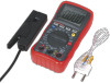
DIGITAL AUTOMOTIVE ANALYSER 13 FUNCTION WITH INDUCTIVE COUPLER Model no: TA201 Thank you for purchasing a Sealey product. Manufactured to a high standard, this product will, if used according to these instructions, and properly maintained, give you years of trouble free performance. IMPORTANT: PLEASE READ THESE INSTRUCTIONS CAREFULLY. NOTE THE SAFE OPERATIONAL REQUIREMENTS, WARNINGS & CAUTIONS. USE THE PRODUCT CORRECTLY AND WITH CARE FOR THE PURPOSE FOR WHICH IT IS INTENDED. FAILURE TO DO SO MAY CAUSE DAMAGE AND/OR PERSONAL INJURY AND WILL INVALIDATE THE WARRANTY. KEEP THESE INSTRUCTIONS SAFE FOR FUTURE USE. Refer to Electrical shock instructions hazard 1. Safety Warning! 1.1. PERSONAL PRECAUTIONS 99 When using this meter, please observe all normal safety rules concerning: Protection against the dangers of electric current. Protection of the meter against misuse. 99 Full compliance with safety standards can only be guaranteed if used with the test leads supplied. If necessary, they must be replaced with genuine Sealey leads with the same electronic ratings. Failure to do so will invalidate the warranty. 88 DO NOT use leads if damaged or if the wire is bared in any way. 1.2. GENERAL SAFETY INSTRUCTIONS 99 Familiarise yourself with the applications, limitations and hazards of the meter. IF IN ANY DOUBT CONSULT A QUALIFIED ELECTRICIAN. 99 When the meter is linked to a measurement circuit, do not touch unused meter terminals. 99 When the scale of the value to be measured is unknown set the selector to the highest range available. 99 Before rotating the rotary switch to change functions, disconnect test leads from the circuit under test. ‰‰ WARNING! Never perform resistance measurements on live circuits. 99 Always be careful when working with voltages above 60Vdc or 30Vac rms. Keep your fingers behind the probe guards while measuring. 99 When not in use, store the meter carefully in a safe, dry, childproof location. Storage temperature range -10°C to 50°C. 88 Never apply voltage or current to the meter that exceeds the specified maximum. 99 The user shall ensure that test probes are correctly selected in order to prevent danger. Probes shall be selected to ensure that adequate barriers guard against inadvertent hand contact with live conductors under test and that probes have minimal exposed probe tips. Where there is a risk of the probe tip short circuiting with other live conductors under test, it is recommended that the exposed tip length shall not exceed 4mm. 99 The warnings, cautions and instructions referred to in this manual cannot cover all possible conditions and situations that may occur. It must be understood that common sense and caution are factors which cannot be built into this product, but must be applied by the operator. I 2. Introduction Compact size meter with four-digit 22mm, high contrast LCD display and back light. Features auto-ranging, data-hold and auto-power-off functions. Includes inductive couplers for fast reading of engine rpm. Supplied with probe, crocodile clip and thermocouple leads for easy hookup. Inductive Coupler Test Probes Function V AC or V DC Input Limits Maximum Input 600V AC, 600V DC mA AC/DC 400mA AC/DC A AC/DC 10A AC/DC (30 secs max every 15 minutes) Frequency Resistance Capacitance Duty Cycle Diode Test Continuity Temperature RPM DWELL Pulse Width 250V AC/DC Test Clips © Jack Sealey Limited Original Language Version fig.1 TA201 Issue 4 (HF) 19/07/18
-
 1
1 -
 2
2 -
 3
3 -
 4
4 -
 5
5
 |
 |
