Sealey TA201 Instruction Manual - Page 4
Maintenance
 |
View all Sealey TA201 manuals
Add to My Manuals
Save this manual to your list of manuals |
Page 4 highlights
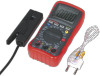
4.8.7. When measuring the forward voltage across a good diode 0.4V or 0.7V will be indicated and the reverse voltage will indicate "OL" (same as on open condition). For a short circuit diode, a value of 0mV will be displayed. ‰‰ WARNING! When checking in-circuit capacitance, be sure to disconnect the power supply from the circuit and that the capacitors are fully discharged. The range control mode in capacitance measurement is auto-ranging. 4.9. Frequency or Duty Cycle measurements 4.9.1. Insert the black test lead into the negative "COM" jack and the red test lead into the positive "Hz" jack. 4.9.2. Turn the rotary switch to the "Hz %DUTY" position. 4.9.3. Press the Hz % button (fig.1.6.) to select Hz or %. 4.9.4. Touch the test probes to the circuit under test and read the frequency or duty cycle on the display. 4.10. Temperature Measurements 4.10.1. Insert the type K thermocouple plug into the negative "COM" jack and the positive jack ensuring the + symbol on the plug is inserted into the positive + jack and the negative symbol on the plug is inserted into the negative "COM" jack. 4.10.2. Turn the rotary switch to the select °C or °F. 4.10.3. Read the temperature on the display. 4.11. RPM (TACHO) Measurements ‰‰ WARNING! To avoid electric shock, ensure the vehicles high tension leads are in good condition and switch off ignition before connecting, disconnecting or relocating the inductive coupler. 4.11.1. Select the RPM or DIS RPM range with the rotary switch. 4.11.2. Select the X10 RPM or DIS X10 RPM range with the rotary switch. Multiply the displayed reading times by 10 to get the actual RPM. 4.11.3. Insert the inductive coupler leads into the meter. Black lead into the negative "COM" jack and the red lead into the positive RPM jack (fig.1.3.). 4.11.4. Connect the inductive coupler to a spark plug HT lead. If no reading is received, unhook the clamp, turn it over and connect again Note: Connect the inductive coupler as far away from the distributor and exhaust manifold as possible. Position the inductive coupler to within six inches of the spark plug or move it to another plug HT lead if no reading or an erratic reading is obtained Note: RPM: For RPM of 4-stroke engines which have 1 ignition on every 4 engine strokes. DIS RPM2: For RPM of DIS (Distributor-less Ignition System) and 2-stroke engines which have 1 ignition on every two strokes. 4.12. Dwell Angle Measurement Dwell angle is the number of degrees through which the distributor cam rotates while the breaker points are closed. 4.12.1. Insert the black test lead into the negative "COM" jack and the red test lead into the positive + jack. 4.12.2. Turn the rotary switch to the corresponding position of 2CYL, 3CYL, 4CYL, 5CYL, 6CYL, 8CYL OR 10CYL on the dwell range. 4.12.3. Connect the black test lead to the Ground terminal (-) on the car battery and the red test lead to the contact breaker points or the negative (-) terminal of the ignition coil. 4.12.4. When the engine is started the Dwell will be displayed. Note: To reduce the dwell angle reading the points gap must be increased, to increase the dwell angle the points gap must be reduced. Refer to your owners handbook for detailed procedures for dwell settings and adjustments. 4.13. Other Functions 4.13.1. Your meter is also capable of testing the following automotive sensors. 4.13.2. Oxygen Sensors Fuel Injectors Temp Sensors Position Sensors absolute pressure (MAP) and Baro Sensors Mass Air Flow (MAF) Sensors 4.13.3. For a detailed description and testing procedure for these sensors, please refer to the vehicles hand book. 4.14. Replacing The Battery ‰‰ WARNING! To avoid electric shock, disconnect the test leads from any source of voltage before removing the battery door. 4.14.1. When the battery become exhausted or drops below the operating voltage, "BAT" will be appear in the right hand side of the display. Replace the battery. 4.14.2. Disconnect the leads from the meter. 4.14.3. Gently pull away the protective plastic moulding cover to gain access to the rear of the meter. 4.14.4. Open the battery door by loosening the two screws using a Philips head screw driver. 4.14.5. Remove the old battery and insert the new one, observing the correct polarity. 4.14.6. Replace the battery cover and secure with the two screws. ‰‰ WARNING! To avoid electric shock, do not operate the meter until the battery cover is secured in place. 4.15. Replacing The Fuses ‰‰ WARNING! To avoid electric shock, disconnect the test leads from any source of voltage before accessing the fuses. 4.15.1. Disconnect the test leads from any item under test and disconnect them from the meter. 4.15.2. Gently pull away the protective plastic moulding cover to gain access to the rear of the meter. 4.15.3. Open the battery door by loosening the two screws using a Philips head screw driver. 4.15.4. Remove the old fuse from its holder by gently pulling it out. 4.15.5. Install the new fuse into its holder. Note: Always use a fuse of the correct size and value. 0.5A/250V fast blow for the 400mA range. 10A/250V fast blow for the 10A range. 4.15.6. Replace the cover and secure with the two screws. ‰‰ WARNING! To avoid electric shock, do not use the meter until it has been fully re-assembled. 5. Maintenance ‰‰ 5.1. 5.2. 88 WARNING! Do not attempt to repair or service your meter unless you are qualified to do so and have the relevant calibration, performance test, and service information. To avoid electrical shock or damage to the meter do not get water inside the case. Periodically wipe the case with a damp cloth and mild detergent. DO NOT use solvents. Turn the meter off when not in use and remove the battery if stored for a long period of time. DO NOT store the meter in a place of high humidity or high temperature. © Jack Sealey Limited Original Language Version TA201 Issue 4 (HF) 19/07/18
-
 1
1 -
 2
2 -
 3
3 -
 4
4 -
 5
5
 |
 |
