Sennheiser ASA 3000 Instructions for Use - Page 4
Operating elements - us
 |
View all Sennheiser ASA 3000 manuals
Add to My Manuals
Save this manual to your list of manuals |
Page 4 highlights
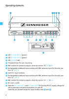
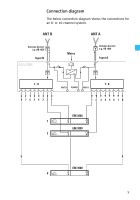
Operating elements ¿ ³· » ¿ µ ¾ º¶ ² ´ ¸ ³ LED DC FEED ANT A (green) · LED DC FEED ANT B (green) » LED POWER (red) ¿ Threaded holes for rack-mounting ´ BNC sockets for antenna outputs, diversity section "B", B1 to B8 ² Exchangeable wideband input module with BNC antenna input for diversity sec- tion "B" ANT. B ¶ Catch for input modules º Exchangeable wideband input module with BNC antenna input for diversity sec- tion "A" ANT. A ¾ BNC sockets for antenna outputs, diversity section "A", A1 to A8 µ IEC mains socket ¸ Switches DC-Feed ANT A and DC-Feed ANT B for turning the DC supply voltage for active antennas and antenna boosters on and off (switches are located inside the input module slots ² and º) 4
-
 1
1 -
 2
2 -
 3
3 -
 4
4 -
 5
5 -
 6
6 -
 7
7 -
 8
8 -
 9
9 -
 10
10 -
11
-
12
-
13
 |
 |

4
Operating elements
±
LED
DC FEED ANT A
(green)
²
LED
DC FEED ANT B
(green)
³
LED
POWER
(red)
´
Threaded holes for rack-mounting
µ
BNC sockets for antenna outputs, diversity section “B”,
B1
to
B8
Exchangeable wideband input module with BNC antenna input for diversity sec-
tion “B”
ANT. B
·
Catch for input modules
¸
Exchangeable wideband input module with BNC antenna input for diversity sec-
tion “A”
ANT. A
¹
BNC sockets for antenna outputs, diversity section “A”,
A1
to
A8
º
IEC mains socket
»
Switches
DC-Feed ANT A
and
DC-Feed ANT B
for turning the DC supply voltage for
active antennas and antenna boosters on and off
(switches are located inside the input module slots
and
¸
)
µ
¹
·
¸
º
²
±
³
´
´
»