Sennheiser Wireless Digital Instructions for Use - Page 8
Connecting additional A 1090 DIGITAL antennas
 |
View all Sennheiser Wireless Digital manuals
Add to My Manuals
Save this manual to your list of manuals |
Page 8 highlights
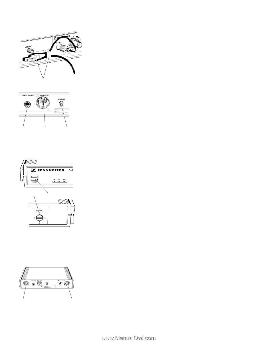
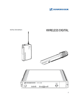
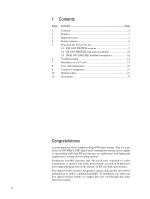
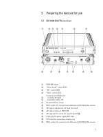
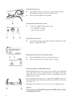
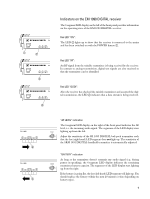
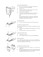
Connecting the mains unit Ǡ Insert the DC connector on the power supply output cable into socket ቯ (refer to page 7) at the rear of the receiver. Ǡ Pass the cable through the cable grip ቮ. ቮ Connecting the amplifier/mixing console Ǡ Connect the amplifier/mixing console either - to the XLR-3M socket ቫ or - to the 1/4" jack socket ቪ. ቪ ቫ ቭ Adjusting the AF output level Ǡ Use the AF output level control ቭ to adjust the AF signal level that appears at outputs ቪ and ቫ. ቨ ቢ Switching the receiver on/off - Selecting a channel Ǡ Press the POWER button ቢ to switch the receiver on. Ǡ Use the channel selector switch ቨ to select a channel. Connecting additional A 1090 DIGITAL antennas Additional digital antennas can be connected to the BNC sockets ቩ and ተ if the range of the receiver's internal antennas is not sufficient. This may happen if receivers are mounted into a rack or are installed between metal constructions on a stage. For connecting the antennas, use 50 Ω coaxial cable with BNC connectors. Ready made up antenna cables from Sennheiser are available as accessories (see chapter 11). Depending on the location you can connect one or two digital antennas. Attention: ቩ ተ Never connect conventional RF antennas to the BNC sockets as these can damage the receiver! 8
-
 1
1 -
2
-
 3
3 -
 4
4 -
 5
5 -
 6
6 -
 7
7 -
 8
8 -
 9
9 -
 10
10 -
 11
11 -
 12
12 -
 13
13 -
14
-
15
-
16
-
17
-
18
-
19
-
20
-
21
-
22
-
23
-
24
-
25
-
26
-
27
-
28
-
29
-
30
-
31
-
32
-
33
-
34
-
35
-
36
-
37
-
38
-
39
-
40
-
41
-
42
-
43
-
44
-
45
-
46
-
47
-
48
-
49
-
50
-
51
-
52
 |
 |