Sharp AN-STWM20 Installation Guide - Page 6
Tube Will Allow, You Can Remove The Screws From The Far End Of The Upper
 |
View all Sharp AN-STWM20 manuals
Add to My Manuals
Save this manual to your list of manuals |
Page 6 highlights
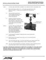
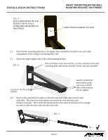
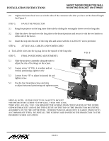
INSTALLATION INSTRUCTIONS SHORT THROW PROJECTOR WALL MOUNTING BRACKET AN-STWM20 2.5 Tighten the button head screws on both sides of the extension tube after you have set the desired length. See Figure 5. STEP 3. HANG THE PROJECTOR 3.1 Hang the projector on the long inner slide tube by sliding the rectangular sleeve over the long tube. 3.2 Slide the sleeve forward over the long tube to the desired position and secure it with the two knobs on either side of the sleeve. 3.4 Insert the stop onto the end of the long tube and secure with the 1/4-20x5/16" screw provided. STEP 4. ATTACH ALL CABLES AND POWER CORD 4. Tuck all the wires into the zig-zag slot on the topside of the long tube. STEP 5. FINAL POSITIONING ADJUSTMENTS. FIG. 6 5.1 Slide the projector assembly along the tube to adjust the size of the image on the screen. 5.2 Loosen screw "A" FIG. 6, to adjust and set vertical positioning, tighten screw 5.3 Loosen Screw "B" to adjust horizontal tilt and tighten screw. 5.3 Use the four mounting screws and slots to adjust horizontal positioning and tighten screws. SPECIAL NOTE: IN THE EVENT YOU WANT TO MOUNT THE PROJECTOR CLOSER TO THE WALL THAN THE LONG TUBE WILL ALLOW, YOU CAN REMOVE THE SCREWS FROM THE FAR END OF THE UPPER SUPPORT BRACKET AND SLIDE THE SLEEVE ON THE TOP OF THE PROJECTOR MOUNTING ASSEMBLY ON TO THE OUTER TUBE. (THE RECTANGULAR SLEEVE IS LARGE ENOUGH TO ACCOMMODATE THIS). RE-INSTALL THE SCREWS AND POSITION THE PROJECTOR TO THE DESIRED CLOSER LOCATION. PAGE 6
-
 1
1 -
 2
2 -
 3
3 -
 4
4 -
 5
5 -
 6
6 -
 7
7 -
 8
8
 |
 |
