Sharp CD-BA3100 CDBA3100 Operation Manual - Page 11
Connections continued
 |
View all Sharp CD-BA3100 manuals
Add to My Manuals
Save this manual to your list of manuals |
Page 11 highlights
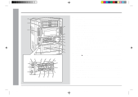
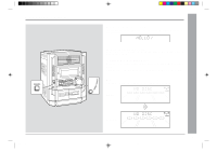
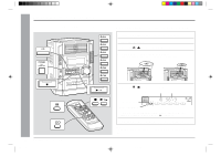
Connections (continued) s Remove the transport screw Before turning the power on, be sure to remove the transport screw on the back of the unit using a flat-blade screwdriver or a coin. Note: This screw is required when transporting the unit again. Please keep it (see page 30). s Speaker connection Main terminals: Connect the lower black wire to MAIN(-) terminal and the blue wire to the MAIN(+) terminal. Subwoofer terminals: Connect the upper black wire to the SUBWOOFER(-) terminal and the red wire to the SUBWOOFER(+) terminal. Right speaker Left speaker s FM/AM loop antenna connection Connect the FM/AM loop antenna to the ANTENNA jack. Position the FM antenna wire and rotate the AM loop antenna for optimum reception. Place the AM loop antenna on a shelf, or attach it to a stand or a wall. Notes: q Placing the antenna on the unit or near the AC power cord may cause noise pickup. Place the antenna away from the unit for better reception. q Do not connect the attached FM antenna to an external FM antenna. Otherwise, trouble may occur. Installing the AM loop antenna: < Assembling > Preparation for Use - System Connections - < Attaching to the wall > , Caution: Red Black Blue Wall Screws (not supplied) q Never mistake the MAIN and the SUBWOOFER terminals. The unit or the speakers may be damaged. ,,,, q Only the included speakers should be used with this product. Do not use other speakers with this unit or use the supplied speakers with other units. q Do not mistake the right and the left channels. The right speaker is the one on the right side when you face the unit. q Do not let the bare speaker wires touch each other. q Do not stand or sit on the speakers. You may be injured. Incorrect s Connecting the AC power cord After checking all the connections have been made correctly, plug the AC power cord of this unit into the AC outlet. If you plug in the unit first, the unit will enter the demonstration mode (see page 13). Note: Unplug the unit if it will not be used for a prolonged period of time. s Demonstration mode (See page 13.) 11 *BA3100_P10_12 11 00.12.8, 4:27 PM
-
 1
1 -
2
-
3
-
4
-
5
-
 6
6 -
 7
7 -
 8
8 -
 9
9 -
 10
10 -
 11
11 -
 12
12 -
 13
13 -
 14
14 -
 15
15 -
 16
16 -
17
-
18
-
19
-
20
-
21
-
22
-
23
-
24
-
25
-
26
-
27
-
28
-
29
-
30
-
31
-
32
 |
 |
