Sharp DV-S2U Service Manual
Sharp DV-S2U Manual
 |
View all Sharp DV-S2U manuals
Add to My Manuals
Save this manual to your list of manuals |
Sharp DV-S2U manual content summary:
- Sharp DV-S2U | Service Manual - Page 1
MODEL DV-S2U CONTENTS Page SPECIFICATIONS ...1-1-1 LASER BEAM SAFETY PRECAUTIONS 1-2-1 IMPORTANT SAFEGUARDS AND PRECAUTIONS 1-3-1 STANDARD NOTES FOR SERVICING 1-4-1 OPERATING CONTROLS AND FUNCTIONS 1-5-1 CABINET DISASSEMBLY INSTRUCTIONS 1-6-1 TEST MODE ...1-7-1 TROUBLESHOOTING ...1-8-1 BLOCK - Sharp DV-S2U | Service Manual - Page 2
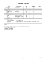
SPECIFICATIONS ITEM 1. Video Output 2. Optical Digital Out 3. Audio (PCM) 3-1. Output Level 3-2. S/N 3-3. Freq. Response DVD CD 3-4. THD+N Other Specifications Power consumption Dimensions Weight CONDITIONS 75 ohm load UNIT Vpp dBm NOMINAL 1.0 -18 LIMIT 1kHz 0dB Vrms 2.0 dB 110 fs=48kHz - Sharp DV-S2U | Service Manual - Page 3
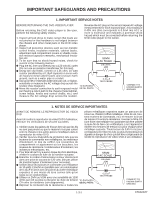
LASER BEAM SAFETY PRECAUTIONS This DVD player uses a pickup that emits a laser beam. Do not look directly at the laser beam coming from the pickup or allow it to strike against your skin. The laser beam is emitted from the location shown in the figure. When checking the laser diode, be sure to keep - Sharp DV-S2U | Service Manual - Page 4
player to the owner. SSVM AC SCALE 1.5k ohms. 10W TO EXPOSED METAL PARTS 0.15 F TEST PROBE CONNECT TO KNOWN EARTH GROUNG 1. NOTES DE SERVICE IMPORTANTES AVANT DE RENDRE LE REPRODUCTOR DE VíDEO pièces métalliques exposées ayant un parcours de DVD retour au châssis (coffret métallique, tétes - Sharp DV-S2U | Service Manual - Page 5
) on AV CBA. A V REFER SERVICING TO QUALIFIED SERVICE PERSONNEL. This symbol warns the user of uninsulated voltage within the unit that can cause dangerous electric shocks. This symbol alerts the user that there are important operating and maintenance instructions in the literature accompanying - Sharp DV-S2U | Service Manual - Page 6
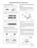
STANDARD NOTES FOR SERVICING Circuit Board Indications a. The output pin of the 3 shown. 5 Pin 1 10 c. The 1st pin of every male connector is indicated as shown. Pin 1 Instructions for Connectors 1. When you connect or disconnect the FFC (Flexible Foil Connector) cable, be sure to first disconnect - Sharp DV-S2U | Service Manual - Page 7
or wire to which solder will not adhere (iron wire). When heating the pins, use a fine tip soldering iron or a hot air desoldering machine. (Fig. S-1-4) Sharp Pin Fine Tip Soldering Iron Fig. S-1-4 (3) Bottom of the flat pack-IC is fixed with glue to the CBA; when removing entire flat pack-IC - Sharp DV-S2U | Service Manual - Page 8
(See Fig. S1-8.) (3) Solder all pins of the flat pack-IC. Be sure that none of the pins have solder bridges. Example : Instructions for Handling Semi-conductors Electrostatic breakdown of the semi-conductors may occur due to a potential difference caused by electrostatic charge during unpacking or - Sharp DV-S2U | Service Manual - Page 9
OPERATING CONTROLS AND FUNCTIONS FRONT PANEL 2 3 45 POWER OPEN/CLOSE PLAY STOP STILL/PAUSE SKIP REV FWD 1 9 87 6 REMOTE CONTROL 1 10 11 12 13 14 15 16 17 18 19 4 20 5 POWER ON SCREEN SETUP OPEN/ CLOSE BLACK DIMMER LEVEL MODE MARKER ZOOM SUBTITLE ANGLE AUDIO TITLE MENU RETURN - Sharp DV-S2U | Service Manual - Page 10
REAR VIEW AUDIO OUT VIDEO OUT COMPONENT Y PR DIGITAL R L VIDEO PB S-VIDEO COMPONENT OUTPUT SELECTOR INTERLACE PROGRESSIVE 32 3334 35 36 37 38 39 32. Power Cord 33. COAXIAL DIGITAL AUDIO OUT Jack 34. Right AUDIO OUT Jack 35. Left AUDIO OUT Jack 36. VIDEO OUT Jack 37. Component Video - Sharp DV-S2U | Service Manual - Page 11
CABINET DISASSEMBLY INSTRUCTIONS 1. Disassembly Flowchart This flowchart indicates the disassembly steps to gain access to item(s) to be serviced. When reassembling, follow the steps in reverse order. Bend, route, and dress the cables as they were originally. [1] Top Cover [2] Front Assembly [3] - Sharp DV-S2U | Service Manual - Page 12
Reference Notes CAUTION 1: Locking Tabs (L-1), (L-2) and (L-3) are fragile. Be careful not to break them. 1-1. Connect the wall plug to an AC outlet and press the OPEN/CLOSE button to open the Tray. 1-2. Remove the Tray Panel by releasing two Locking Tabs (L-1). 1-3. Press the OPEN/CLOSE button - Sharp DV-S2U | Service Manual - Page 13
DVD Mecha A B Short the three short lands by soldering View for A OR Slide Short the three short lands by soldering C Pickup Unit View for B View for C Fig. 4 (S-4) [7] Progure PCB Shield (S-5) [5] DVD Main CBA Shield CN1801 [8] Progressive CBA Unit CN1802 Insulator Sheet (S-6) (L-4) - Sharp DV-S2U | Service Manual - Page 14
the eject-bar (length = approximately 80 mm, diameter = approximately 3 mm) into the manual eject hole on the DVD Mecha. Then, press it until the tray is ejected. Top Case Tray DVD Mecha Manual Eject Hole Eject-Bar (Length = approximately 80 mm, Diameter = approximately 3 mm) 1-6-4 E56B0DC - Sharp DV-S2U | Service Manual - Page 15
TEST MODE Test Mode ROM Renewal Mode A power source is put, and [1], [2], [3], [4], and [ON SCREEN] buttons on the remote control unit are pushed in that order while the tray is opening or after the "NO DISC" display at the same time. A power source is put, and [9], [8], [7], [6], and [DIRECT SKIP - Sharp DV-S2U | Service Manual - Page 16
FE . BE . AVD . DSP . 1. TEST1 - VFD 2. TEST2 - REPEAT PLAY 3. TEST3 - EEPROM CLEAR 4. TEST4 - MEASUREMENT SERVO RETURN: RETURN EXIT: POWER Fig. T-1: Test Mode Initial Display FE . BE . TEST1 - VFD 1. ON 2. OFF VFD STATUS AVD . DSP . [ --- ] RETURN: RETURN EXIT: POWER Fig. T-2: All VFD ON/ - Sharp DV-S2U | Service Manual - Page 17
[ROM RENEWAL MODE] 1. Turn the power on and remove the disc on the tray. 2. To put the DVD player into version up mode, press [9], [8], [7], [6], and [DIRECT SKIP] buttons on the remote control unit in that order. The tray will open automatically. Fig. a appears on the screen and Fig. b appears on - Sharp DV-S2U | Service Manual - Page 18
[ ERROR RATE MEASUREMENT] 1. Turn the power on, remove the disc from the tray and close the tray. 2. To put the DVD player into test mode, press [1], [2], [3], [4], and [ON SCREEN] buttons on the remote control unit in that order. Fig. a will appear on the screen and the current B/E version will - Sharp DV-S2U | Service Manual - Page 19
E56***D FE *.*** BE *.*** AVD *.* TEST4-MEASUREMENT MODE DISC:DVD / DUAL LAYER / OPPOSITE END:******H / ******H STATUS PLAY MODE-ERROR RATE 1. L-0/030000 HEX 2. L-0/220000 HEX 3. L-1/FC0000 HEX 4. L-1/E00000 HEX RETURN: RETURN POWER EXIT: (I) when loading DVD DISC:DVD / DUAL LAYER / OPPOSITE - Sharp DV-S2U | Service Manual - Page 20
The fuse blows out. Check the presence that the primary component is leaking or short then service it if defective. After servicing, replace the fuse. See FLOW CHART No.2 Check if there the key switches (SW2011-2014, 2016, 2017), and their periphery circuit. TROUBLESHOOTING - Sharp DV-S2U | Service Manual - Page 21
E56B0TS 1-8-2 FLOW CHART NO.7 No operation is possible from the remote control unit. Operation is possible from the DVD, but no operation is possible from the remote control unit. Yes Is no operation possible if replacing the remote No control unit? Yes No Is 5V voltage supplied to Pin(3) - Sharp DV-S2U | Service Manual - Page 22
E56B0TS 1-8-3 FLOW CHART NO.14 The disc tray cannot be opened and closed. Replace the DVD Main CBA Unit. No No improvement can be found. Yes Replace the DVD Mecha. FLOW CHART NO.15 [No Disc] is indicated. (When the focus error occur.) Replace the DVD Main CBA Unit. No improvement can be found. - Sharp DV-S2U | Service Manual - Page 23
E56B0TS 1-8-4 FLOW CHART NO.19 Picture does not appear normally in interlace mode. Set the disc on the disc tray and playback. No Are the video signals outputted to each pin of CN1601 on the the AV CBA? CN1601 7PIN CN1601 5PIN CN1601 9PIN CN1601 3PIN CN1601 1PIN CVBS S-Y S-C U V Yes Are the - Sharp DV-S2U | Service Manual - Page 24
E56B0TS 1-8-5 FLOW CHART NO.21 Audio is not outputted. Set the disc on the disc tray and playback. No Are the analog audio signals outputted to each pin of CN1601 on the AV CBA? CN1601 13PIN AUDIO-L CN1601 15PIN AUDIO-R Yes Are the analog audio signals inputted to each pin of IC1201. No - Sharp DV-S2U | Service Manual - Page 25
System Control Block Diagram BLOCK DIAGRAMS FROM/TO RF SIGNAL PROCESS /SERVO BLOCK DIAGRAM FROM/TO DVD SIGNAL PROCESS BLOCK DIAGRAM FG SENSOR FG CBA TFWD TREV TIN TOUT SCK STDIO SEN MUTE PS IC301 (FRONT END PROCESSOR) 42 TFWD 41 TREV 59 TIN 60 TOUT 70 SCK 72 STDIO 10 SEN 46 MUTE 47 PS +3.3V - Sharp DV-S2U | Service Manual - Page 26
RF Signal Process/Servo Block Diagram PICK-UP UNIT DETECTOR A B C D F E CD/DVD CN101 6 9 10 7 4 5 21 TS FS CD-LD DVD-LD PD-MONI GND(DVD-PD) GND(LD) GND(CD-PD) CN101 Q102 20 AMP 12 AMP Q101 11 14 13 19 13 IC103 (SW) 6 4 FS(+) FS(-) TS(+) TS(-) CN101 17 16 15 18 LOADING M MOTOR - Sharp DV-S2U | Service Manual - Page 27
DVD Signal Process Block Diagram IC201 (DVD SIGNAL PROCESS) ARF FROM/TO RF SIGNAL NARF 111 PROCESS/SERVO 110 BLOCK DIAGRAM TESTSG 82 PLL VCO DATA SLICER BCA DVD DEMODULATOR FROM/TO SYSTEM CONTROL BLOCK DIAGRAM ADDRESS BUS DATA BUS NINT1 NINT2 WAIT /RE /WEL CS1 RESET ~ ~~ ~ ~ 30 - Sharp DV-S2U | Service Manual - Page 28
Video Block Diagram DATA(VIDEO) SIGNAL DATA(AUDIO) SIGNAL VIDEO SIGNAL DATA(VIDEO/AUDIO) SIGNAL IC601 (DVD HOST PROCESSOR) FROM DVD SIGNAL PROCESS BLOCK DIAGRAM PARA0-PARA7 ~ 6 PARA0 13 PARA7 ~ FROM/TO PROGRESSIVE BLOCK DIAGRAM CN1801 CN702 YC(0-7) 3-10 SDA 13 SCL 14 /FERS 15 - Sharp DV-S2U | Service Manual - Page 29
Progressive Block Diagram CN1801 FROM/TO VIDEO BLOCK DIAGRAM CN702 3-10 YC(0-7) 13 SDA 14 SCL 1 CLK27MHz 16 H SYNC 17 FID 15 /FERS IC1801 (DE-INTERLACER) 20 FORMATTER DE-INTERLACER 27 40 PLL/CLOCK GENE 3 4 ~ RESET SDA SCL ADDR0 ADDR10 DATA0 DATA31 ~ ~ 49 47 48 125~136 139~ 176 - Sharp DV-S2U | Service Manual - Page 30
Audio Block Diagram DATA(AUDIO) SIGNAL AUDIO SIGNAL SPDIF PCM-BCK PCM-DATA0 PCM-LRCLK FROM VIDEO BLOCK DIAGRAM ADAC-MD ADAC-MC ADAC-ML PCM-SCLK A-MUTE IC801 (AUDIO DAC) 4X/8X 1 2 3 SERIAL PORT OVERSAMPLING DIGITAL FILTER /FUNCTION CONTROLLER ENPHANCED MULTI-LEVEL DELTA-SIGMA MODULATOR - Sharp DV-S2U | Service Manual - Page 31
Power Supply Block Diagram CAUTION ! Switching power supply circuit is used in this unit. If Main Fuse (F1001) is blown, check to see that all components in the power supply circuit are not defective before you connect the AC plug to the AC power supply. Otherwise it may cause some components in the - Sharp DV-S2U | Service Manual - Page 32
identified by the mark " # " in the schematic diagram and the parts list. Before replacing any of these components, read the parts list in this manual carefully. The use of substitute replacement parts that do not have the same safety characteristics as specified in the parts list may create shock - Sharp DV-S2U | Service Manual - Page 33
of repaired units, use only original replacement parts which are listed with their part numbers in the parts list section of the service manual. 4. Wire Connectors (1) Prefix symbol "CN" means "connector" (can disconnect and reconnect). (2) Prefix symbol "CL" means "wire-solder holes of the PCB - Sharp DV-S2U | Service Manual - Page 34
DVD Main 1/4 Schematic Diagram MAIN 1/4 Ref No. Position ICS IC101 C-4 IC102 F-5 IC103 B-3 IC301 E-2 TRANSISTORS Q101 B-3 Q102 B-3 CONNECTORS CN101 A-4 CN302 G-2 CN501 A-2 1-10-3 1-10-4 1-10-5 E56B0SCD1 - Sharp DV-S2U | Service Manual - Page 35
DVD Main 2/4 Schematic Diagram MAIN 2/4 Ref No. Position ICS IC201 N-2 IC401 I-3 TRANSISTOR Q401 I-3 CONNECTORS CN201 N-1 CN401 H-4 1-10-6 1-10-7 1-10-8 E56B0SCD2 - Sharp DV-S2U | Service Manual - Page 36
DVD Main 3/4 Schematic Diagram MAIN 3/4 Ref No. Position ICS IC601 T-1 IC602 P-3 IC605 O-5 IC606 O-4 IC607 P-4 TRANSISTOR Q701 P-5 CONNECTOR CN702 U-4 1-10-9 1-10-10 1-10-11 E56B0SCD3 - Sharp DV-S2U | Service Manual - Page 37
DVD Main 4/4 Schematic Diagram AV 1/3 Schematic Diagram 1-10-12 MAIN 4/4 Ref No. Position ICS IC604 W-2 IC801 Y-1 CONNECTOR CN701 AA-2 1-10-13 E56B0SCD4 AV 1/3 Ref No. Position ICS IC1001 B-1 IC1002 D-3 IC1003 D-2 IC1006 C-1 TRANSISTORS Q1001 B-2 Q1002 D-3 Q1003 B-2 - Sharp DV-S2U | Service Manual - Page 38
AV 2/3 Schematic Diagram AV 2/3 Ref No. Position ICS IC1201 G-1 IC1402 H-3 TRANSISTORS Q1201 H-1 Q1202 H-1 Q1203 H-1 Ref No. Position TRANSISTORS Q1204 H-1 Q1351 I-1 CONNECTOR CN1601 F-3 CN1602 J-2 1-10-15 1-10-16 E56B0SCAV2 - Sharp DV-S2U | Service Manual - Page 39
AV 3/3 & Switch Schematic Diagram 7G 6G 5G 4G 3G 2G 1G STANDBY REPEAT A-B TITLE CHP. TRK. a DVD 1 2 c b VCD 3 d PBC 4 f ge 5 FL2001 MATRIX CHART 7G 6G 5G 4G a STANDBY a a a b REPEAT b b b cA c c c d -B d d d e e e e f f f f g g g g h TITLE i 3G 2G 1G a - Sharp DV-S2U | Service Manual - Page 40
Progressive Schematic Diagram PROGRESSIVE Ref No. Position ICS IC1801 B-4 IC1802 F-4 IC1803 F-2 IC1805 B-4 IC1806 A-1 IC1807 A-1 IC1808 C-5 IC1809 E-5 CONNECTOR CN1801 A-3 CN1802 G-5 1-10-19 1-10-20 1-10-21 E56B0SCPR - Sharp DV-S2U | Service Manual - Page 41
DVD Main CBA Top View 1-10-22 1-10-23 1-10-24 BE5600G04011 - Sharp DV-S2U | Service Manual - Page 42
DVD Main CBA Bottom View 1-10-25 1-10-26 1-10-27 BE5600G04011 - Sharp DV-S2U | Service Manual - Page 43
IN THE POWER SUPPLY CIRCUIT, AN ISOLATION TRANSFORMER MUST BE USED. ALSO, IN ORDER TO HAVE THE ABILITY TO INCREASE THE INPUT SLOWLY, WHEN TROUBLESHOOTING THIS TYPE POWER SUPPLY CIRCUIT, A VARIABLE ISOLATION TRANSFORMER IS REQUIRED. WF1 WF2 WF3 WF4 WF5 WF6 PIN 5 OF PIN 7 OF PIN 9 OF PIN 13 - Sharp DV-S2U | Service Manual - Page 44
Progressive CBA Top View 1-10-31 1-10-32 BE5635F02011 - Sharp DV-S2U | Service Manual - Page 45
Progressive CBA Bottom View 1-10-33 1-10-34 BE5635F02011 - Sharp DV-S2U | Service Manual - Page 46
WF1 Pin 5 of CN1601 VIDEO-Y 0.2V 20usec WF2 Pin 7 of CN1601 WAVEFORMS WF5 Pin 15 of CN1601 AUDIO-R 1V 0.5msec WF6 Pin 18 of CN1601 NOTE: Input CD: 1kHz PLAY (WF4~WF6) DVD: POWER ON (STOP) MODE (WF1~WF3) VIDEO-CVBS 0.5V 20usec WF3 Pin 9 of CN1601 SPDIF 1V 0.2usec VIDEO-C 0.2V 20usec - Sharp DV-S2U | Service Manual - Page 47
E56B0WI 1-12-2 1-12-1 CN1802 1 2 3 4 5 6 7 8 9 10 11 12 PROGRESSIVE CBA UNIT CN1801 1 2 3 4 5 6 7 8 9 10 11 12 13 14 15 16 17 18 18 GND 17 FID PICK UP UNIT DETECTOR DVD MECHA 16 H-SYNC 15 /FERS 14 SCL 13 SDA TRAY-IN RELAY CBA SPINDLE MOTOR M SLIDE MOTOR M 12 NU 11 GND 10 YC0 SW CBA - Sharp DV-S2U | Service Manual - Page 48
SYSTEM CONTROL TIMING CHARTS Tray close ~ Play / Play ~ Tray open Eject key on Tray close Disc Play Rotation LSW2 0V LSW1 +5V +6V LM- 0V +6V LM+ 0V +2V I/o 0V (TL123) +5V SP 0V ( TP122 ) +2V Tv 0V ( TL122 ) 4.4s 2.0s 1.2s 1.7s Eject key on Tray open 700ms 1-13-1 - Sharp DV-S2U | Service Manual - Page 49
IC PIN FUNCTION DESCRIPTIONS IC2001 ( PT6315-S ) Pin No. In/Out 1 In Signal Name CLK Name Function Clock Input 2 In STB Serial Interface Strobe 3 In K1 Key Data 1 Input 4 In K2 Key Data 2 Input 5 - VSS GND 6 - VDD Power Supply 7 Out a / KEY-1 Segment Output / Key Souce-1 8 Out - Sharp DV-S2U | Service Manual - Page 50
LEAD IDENTIFICATIONS 2SA1015-Y (TPE2) KTC3205 (Y) 2SC2236-Y-TPE6,C 2SC2785 (H) KTC3199 (GR) KRA110M KRC110M-AT BA1L3Z-T BN1L3Z (P) KTA1266 (Y) 2SK3374 E C B E C B G D S PQ018EF01SZ NJM4558D KIA4558P 8 5 PT6315-S PT6315-S(-TP) 28 15 KIA431-AT 1 4 1 4 1 14 R A K MM1567AJ 34 18 1 - Sharp DV-S2U | Service Manual - Page 51
Cabinet 2L011 EXPLODED VIEWS 2L011 A16 See Electrical Parts List for parts with this mark. Some Ref. Numbers are not in sequence. 2B24 2L031 2B22 2L051 A2 2L021 2L011 2L011 2L021 2L021 1B1 2B23 DVD Main CBA Unit 2L104 2L103 W1001 2B15 2L031 2B21 W1602 W1601 2B4 JK1403 JK1201 F1001 - Sharp DV-S2U | Service Manual - Page 52
Packing X14 X31 X10A X5 X2 S2 X1 X4 S4 S2 Unit A22 S1 1-16-2 E56B0EX - Sharp DV-S2U | Service Manual - Page 53
special characteristics important to safety. Before replacing any of these components, read carefully the product safety notice in this service manual. Don't degrade the safety of the product through improper servicing. Ref. No. A1X A2 A13 A15 A16 A17 A21# A22 1B1 2B2 2B15 2B20 2B21 2B22 2B23 2B24 - Sharp DV-S2U | Service Manual - Page 54
to safety. Before replacing any of these components, read carefully the product safety notice in this service manual. Don't degrade the safety of the product through improper servicing. NOTES: 1. Parts that not assigned part numbers are not available. 2. Tolerance of Capacitors and Resistors are - Sharp DV-S2U | Service Manual - Page 55
Ref. No. C209 C210 C211 C212 C213 C214 C215 C216 C217 C218 C219 C220 C221 C222 C223 C224 C225 C226 C227 C228 C229 C230 C231 C231 C232 C232 C233 C233 C234 C235 C236 C240 C301 C302 C303 C304 C305 C306 C309 C310 C311 C401 C402 C403 C404 C408 C408 C409 C410 C411 C412 C414 C415 C416 C417 C418 C419 C420 - Sharp DV-S2U | Service Manual - Page 56
Ref. No. C607 C608 C608 C609 C610 C611 C613 C614 C616 C617 C618 C619 C620 C621 C622 C625 C625 C701 C703 C707 C709 C710 C711 C715 C722 C723 C751 C753 C757 C759 C761 C762 C773 C774 C801 C801 C802 C803 C803 C804 C805 C805 CN101 CN201 CN302 CN401 CN501 CN701 CN702 D301 D702 IC101 IC102 IC103 IC201 IC301 - Sharp DV-S2U | Service Manual - Page 57
Ref. No. IC801 L501 L601 L602 L603 L604 Q101 Q102 Q401 Q401 Q701 Q701 R102 R103 R106 R107 R108 R111 R112 R113 R113 R116 R117 R117 R119 R120 R121 R122 R125 R126 R127 R128 R129 R130 R131 R133 R133 R134 R134 R135 R136 R138 R143 R144 R155 R156 R160 R163 R164 R168 R169 R170 R171 R203 R203 R205 R206 R207 - Sharp DV-S2U | Service Manual - Page 58
Ref. No. R224 R224 R225 R226 R227 R228 R229 R230 R231 R232 R234 R235 R236 R237 R239 R240 R241 R242 R301 R302 R303 R304 R305 R306 R308 R309 R310 R311 R312 R313 R314 R315 R316 R317 R317 R320 R321 R322 R323 R324 R325 R331 R332 R334 R336 R337 R401 R402 R403 R404 R405 R406 R407 R408 R409 R410 R411 R412 - Sharp DV-S2U | Service Manual - Page 59
Ref. No. R603 R604 R605 R606 R607 R608 R609 R610 R611 R612 R615 R616 R616 R618 R618 R620 R622 R624 R625 R626 R627 R627 R628 R628 R629 R634 R637 R701 R701 R702 R703 R706 R706 R709 R711 R712 R713 R714 R716 R717 R718 R719 R720 R721 R721 R722 R723 R724 R725 R727 R728 R729 R731 R734 R735 R751 R752 R761 - Sharp DV-S2U | Service Manual - Page 60
PROGRESSIVE CBA UNIT Ref. No. C1801 C1802 C1803 C1804 C1805 C1806 C1807 C1810 C1811 C1812 C1813 C1814 C1815 C1816 C1817 C1818 C1819 C1820 C1821 C1822 C1823 C1824 C1825 C1826 C1827 C1828 C1829 C1830 C1831 C1832 C1835 C1836 C1837 C1838 C1839 C1841 C1842 C1843 C1844 C1845 C1846 C1847 C1848 C1849 C1850 - Sharp DV-S2U | Service Manual - Page 61
Ref. No. IC1809 L1801 L1802 L1802 L1803 L1803 L1804 L1805 L1806 L1807 L1808 L1809 L1810 L1811 L1812 L1813 L1813 L1814 L1814 R1801 R1801 R1802 R1802 R1803 R1805 R1806 R1808 R1808 R1810 R1811 R1812 R1813 R1814 R1815 R1816 R1817 R1818 R1819 R1820 R1821 R1822 R1823 R1824 R1825 R1827 R1828 R1829 R1830 - Sharp DV-S2U | Service Manual - Page 62
AV CBA + SWITCH CBA Ref. No. AV CBA + SWITCH CBA Consists of the following AV CBA SWITCH CBA Description AV CBA Ref. No. C1001# C1001# C1001# C1003 C1003 C1004 C1005 C1006# C1006# C1007 C1012 C1013 C1014 C1017 C1018 C1021 C1022 C1029 C1031 C1032 C1033 C1035 C1036 C1037 C1038 C1039 C1040 C1041 - Sharp DV-S2U | Service Manual - Page 63
Ref. No. C1421 C1422 C1422 C1441 C1442 C1445 C1461 C1462 C1481 C1482 C1522 C1523 C1531 C1532 C2001 C2002 C2004 C2008 C2012 C2055 C2057 C2057 CN1001 CN1601 CN1602 D1001 D1002 D1003 D1003 D1004 D1005 D1008 D1009 D1009 D1011 D1011 D1012 D1013 D1015 D1016 D1016 D1017 D1018 D1022 D1024 D1025 D1030 D1030 - Sharp DV-S2U | Service Manual - Page 64
Ref. No. IC1201 IC1402 IC2001 L1001# L1006 L1007 L1008 L1009 L1011 L1043 L1060 L1251 L1521 L2001 L2002 L2003 L2801 L2801 Q1001 Q1002 Q1002 Q1003 Q1003 Q1004 Q1005 Q1006 Q1006 Q1007 Q1008 Q1008 Q1011 Q1014 Q1014 Q1201 Q1201 Q1202 Q1202 Q1203 Q1203 Q1204 Q1204 Q1351 Q1351 Q1603 Q1603 R1002 R1002 R1004 - Sharp DV-S2U | Service Manual - Page 65
Ref. No. R1025 R1029 R1029 R1030 R1031 R1032 R1032 R1033 R1034 R1035 R1035 R1036 R1036 R1037 R1037 R1038 R1038 R1039 R1039 R1042 R1043 R1044 R1049 R1059 R1068 R1068 R1069 R1069 R1070 R1070 R1071 R1071 R1073 R1075 R1077 R1078 R1078 R1201 R1202 R1203 R1203 R1204 R1204 R1205 R1206 R1207 R1208 R1209 - Sharp DV-S2U | Service Manual - Page 66
Ref. No. R1246 R1247 R1352 R1352 R1353 R1354 R1355 R1356 R1356 R1392 R1393 R1394 R1395 R1401 R1402 R1402 R1421 R1422 R1422 R1441 R1442 R1442 R1443 R1443 R1461 R1462 R1462 R1481 R1482 R1482 R1521 R1608 R1609 R1610 R1610 R2001 R2002 R2003 R2005 R2006 R2031 R2032 R2034 R2037 R2037 R2038 R2039 R2059 - Sharp DV-S2U | Service Manual - Page 67
Ref. No. JK1403 RM2001 SA1001# SA1001# SA1001# T1001# W1001 W1601 W1602 Description RCA JACK MSP-244V10-46 PBSN REMOTE RECEIVER PIC-37043LU SURGE ABSORBER PVR-10D471KB SURGE ABSORBER CNR-10D471K SURGE ABSORBER JVR-10N471K PULSE TRANS CSA-SW0061 26P FFC AV PCB TO MAIN 18P FFC 12P FFC AV PCB TO PRS - Sharp DV-S2U | Service Manual - Page 68
DV-S2U COPYRIGHT © 2002 BY SHARP CORPORATION ALL RIGHTS RESERVED. No part of this publication may be reproduced, , without prior written permission of the publisher. Jan. 2002 Printed in JAPAN SHARP CORPORATION AV Systems Group Quality & Reliability Control Center Yaita, Tochigi 329-2193, Japan 1
-
 1
1 -
 2
2 -
 3
3 -
 4
4 -
 5
5 -
 6
6 -
 7
7 -
8
-
9
-
10
-
11
-
12
-
13
-
14
-
15
-
16
-
17
-
18
-
19
-
20
-
21
-
22
-
23
-
24
-
25
-
26
-
27
-
28
-
29
-
30
-
31
-
32
-
33
-
34
-
35
-
36
-
37
-
38
-
39
-
40
-
41
-
42
-
43
-
44
-
45
-
46
-
47
-
48
-
49
-
50
-
51
-
52
-
53
-
54
-
55
-
56
-
57
-
58
-
59
-
60
-
61
-
62
-
63
-
64
-
65
-
66
-
67
-
68
 |
 |
DV-S2U
S12E4DV-S2U//
SERVICE MANUAL
Page
SPECIFICATIONS
.............................................................................................................................
1-1-1
LASER BEAM SAFETY PRECAUTIONS
..........................................................................................
1-2-1
IMPORTANT SAFEGUARDS AND PRECAUTIONS
.........................................................................
1-3-1
STANDARD NOTES FOR SERVICING
.............................................................................................
1-4-1
OPERATING CONTROLS AND FUNCTIONS
..................................................................................
1-5-1
CABINET DISASSEMBLY INSTRUCTIONS
.....................................................................................
1-6-1
TEST MODE
......................................................................................................................................
1-7-1
TROUBLESHOOTING
.......................................................................................................................
1-8-1
BLOCK DIAGRAMS
...........................................................................................................................
1-9-1
SCHEMATIC DIAGRAMS/ CBA’S AND TEST POINTS
..................................................................
1-10-1
WAVEFORMS
..................................................................................................................................
1-11-1
WIRING DIAGRAM
..........................................................................................................................
1-12-1
SYSTEM CONTROL TIMING CHARTS
..........................................................................................
1-13-1
IC PIN FUNCTION DESCRIPTIONS
...............................................................................................
1-14-1
LEAD IDENTIFICATIONS
................................................................................................................
1-15-1
EXPLODED VIEWS
.........................................................................................................................
1-16-1
MECHANICAL PARTS LIST
............................................................................................................
1-17-1
ELECTRICAL PARTS LIST
.............................................................................................................
1-18-1
CONTENTS
In the interests of user-safety (Required by safety regula-
tions in some countries) the set should be restored to its
original condition and only parts identical to those specified
be used.
MODEL
DV-S2U
SERVICE MANUAL
DVD VIDEO PLAYER
MODEL
DV-S2U
DVD VIDEO PLAYER
This document has been published to be used for
after sales service only.
The contents are subject to change without notice.
SHARP CORPORATION
PLAY
STOP
STILL/PAUSE
OPEN/CLOSE
SKIP
REV
FWD
POWER