Sharp DV-S2U Service Manual - Page 8
Instructions for Handling, Semi-conductors, Installation, Ground for Human Body, Ground for Workbench
 |
View all Sharp DV-S2U manuals
Add to My Manuals
Save this manual to your list of manuals |
Page 8 highlights
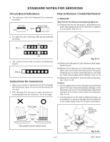
2. Installation (1) Using desoldering braid, remove the solder from the foil of each pin of the flat pack-IC on the CBA so you can install a replacement flat pack-IC more easily. (2) The " " mark on the flat pack-IC indicates pin 1. (See Fig. S-1-7.) Be sure this mark matches the 1 on the PCB when positioning for installation. Then presolder the four corners of the flat pack-IC. (See Fig. S1-8.) (3) Solder all pins of the flat pack-IC. Be sure that none of the pins have solder bridges. Example : Instructions for Handling Semi-conductors Electrostatic breakdown of the semi-conductors may occur due to a potential difference caused by electrostatic charge during unpacking or repair work. 1. Ground for Human Body Be sure to wear a grounding band (1MΩ) that is properly grounded to remove any static electricity that may be charged on the body. 2. Ground for Workbench Be sure to place a conductive sheet or copper plate with proper grounding (1MΩ) on the workbench or other surface, where the semi-conductors are to be placed. Because the static electricity charge on clothing will not escape through the body grounding band, be careful to avoid contacting semi-conductors with your clothing. Pin 1 of the Flat Pack-IC is indicated by a " " mark. Fig. S-1-7 < Incorrect > Presolder CBA CBA Flat Pack-IC Fig. S-1-8 < Correct > Grounding Band CBA Conductive Sheet or Copper Plate 1-4-3 DVD_NOTE
-
 1
1 -
2
-
 3
3 -
 4
4 -
 5
5 -
 6
6 -
 7
7 -
 8
8 -
 9
9 -
 10
10 -
 11
11 -
 12
12 -
 13
13 -
14
-
15
-
16
-
17
-
18
-
19
-
20
-
21
-
22
-
23
-
24
-
25
-
26
-
27
-
28
-
29
-
30
-
31
-
32
-
33
-
34
-
35
-
36
-
37
-
38
-
39
-
40
-
41
-
42
-
43
-
44
-
45
-
46
-
47
-
48
-
49
-
50
-
51
-
52
-
53
-
54
-
55
-
56
-
57
-
58
-
59
-
60
-
61
-
62
-
63
-
64
-
65
-
66
-
67
-
68
 |
 |
