Sharp KB-6014LW Installation Manual - Page 3
Microwave Drawer Measurements, Anti-tip Block
 |
View all Sharp KB-6014LW manuals
Add to My Manuals
Save this manual to your list of manuals |
Page 3 highlights
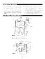
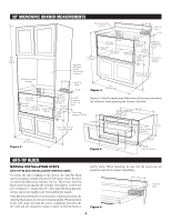
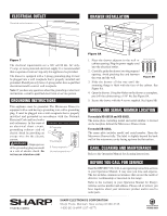
30" MICROWAVE DRAWER MEASUREMENTS Electrical outlet location 5" 6" Anti-Tip block 3 1/2" 84" wall cabinet Electrical outlet location 5" Optional wall oven cutout illustrated in sketch coun3t6e"rtop height 4" 2op8e7n/in16g " Aovlleorwla3p./4" m2in3d1e/2pt" h Allow 3/4" overlap. Allow 1/4" overlap. 14 3/4" opening Allow 7ov/1e6rl"ap. 14 13/16" to bottom of Anti-Tip block Floor must support 100 lbs. 19" to top of floor (recommended) (6") Anti-Tip block 3 1/2" 30" cabinet min. Figure 4 28 7/16" 4" opening Allow 3/4" overlap. 23 1/2" min depth Allow 3/4" overlap. 2" min. Allow 1/4" overlap. 14 3/4" opening Allow 7/16" overlap. 14 13/16" to bottom of Anti-Tip block Floor must support 100 lbs. Figures 3, 4 and 5 contain many Microwave Drawer measurements for reference when planning the drawer's location. 2" 4 11/16" 28 1/8" 19" to top of floor (recommended) 15 13/32" 15" auto drawer opening 14 3/4" 30" cabinet min. Figure 3 Figure 5 30" 23 3/8" ANTI-TIP BLOCK NORMAL INSTALLATION STEPS ANTI-TIP BLOCK INSTALLATION INSTRUCTIONS To reduce the risk of tipping of the drawer, the Anti-Tip block must be properly installed located E1l4ec3tr/i4ca-linoucthleetsloacbaotivoen the floor on which the Microwave Drawer will sit. The 6-inch Anti-Tip block must be provided by the installer. See Figures 1 and 6 (for 24") or Figures 3, 4 and 6 (for 30"). The Anti-Tip block prevents serious injury that might result from spilled hot liquids. If the Microwave Drawer is ever moved to a different location, the Anti-Tip block must also be moved and installed. When installed to the wall, make sure that the screws completely penetrate the dry wall and are secured in wood or metal so that the block is totally stable. When fastening, be sure that the screws do not penetrate electrical wiring or plumbing. (6") Anti-Tip block 5" 4" Figure 6 3
-
 1
1 -
 2
2 -
 3
3 -
 4
4
 |
 |
