Sharp KB3300JK Service Manual - Page 44
Drawer Assembly And Choke Removal, Drawer Support Angle Removal, Drawer/slide Rail Removal
 |
UPC - 074000612334
View all Sharp KB3300JK manuals
Add to My Manuals
Save this manual to your list of manuals |
Page 44 highlights
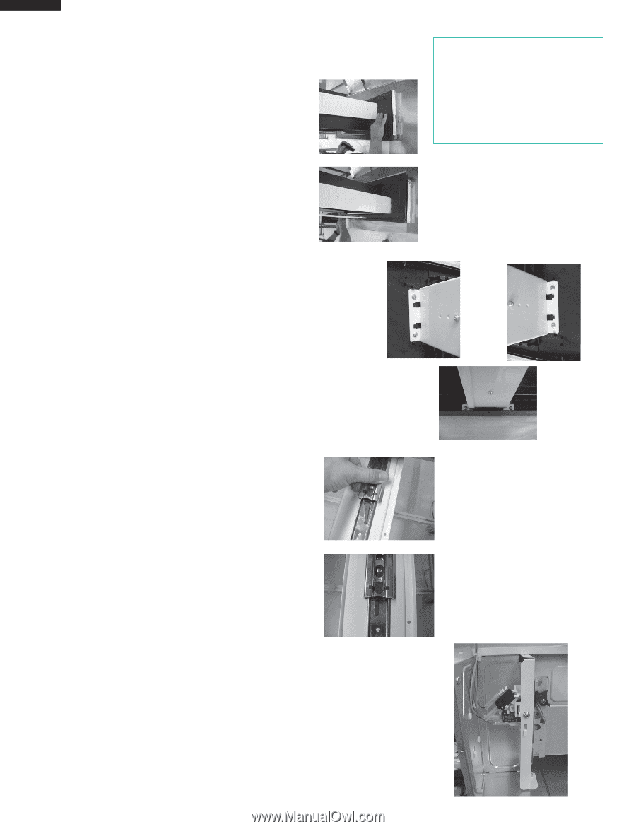
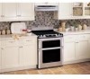
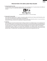
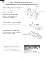
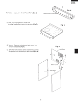
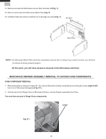
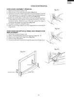
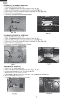
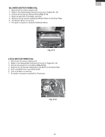
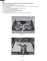
KB-3300JS KB-3300JK KB-3300JW DRAWER/SLIDE RAIL REMOVAL DRAWER ASSEMBLY AND CHOKE REMOVAL 1. Disconnect the power supply cord. 2. Open the drawer and keep it open. Fig. D-1 3. To discharge the high voltage capacitor, wait for 60 seconds. 4. Remove the both right and left Cook Top Stays. 5. Remove (2) Drawer Support Covers from Choke Cover as shown in (Fig. D-1). 6. Insert a putty knife (thickness of about 0.5mm) into the gap between the choke cover and the door frame. 7. Carefully slide choke cover away from drawer as far as possible. 8. Remove (6) screws from all (3) drawer Support Angles as shown in (Fig. D-2). 9. Unhook Drawer Support Angles from drawer, then remove. 10.Now, the door assembly is free and the Choke Cover can now be removed. DRAWER SUPPORT ANGLE REMOVAL 1. Remove Drawer Assembly and Choke Cover as stated in "DRAWER ASSEMBLY AND CHOKE REMOVAL". 2. Remove (2) screws from right or left Latch Angle Assembly, then remove Angle assembly (Fig. D-4). 3. Separate Slide Rails by moving inside lever of Slide Rails. The Slide Rail will now separate by pulling straight forward and out (Fig. D-3). 4. At this point, you can replace either Latch Angle Assy or Latch Angles. To reassemble, just reverse the above order. After reassembly, do the following. (A) Make sure that drawer sensing switch, secondary interlock switch and monitor switch are operating properly. (Refer to chapter "Test Procedures".) (B) An approved microwave survey meter should be used to assure compliance with proper microwave radiation emission limitation standards. After any servicing, make sure of the following : 1. Drawer latch heads smoothly catch latch hook through latch holes and that latch head goes through center of latch hole. 2. Deviation of door alignment from horizontal line of cavity face plate is to be less than 1.0mm. 3. Drawer is positioned with its face pressed toward cavity face plate. 4. Reassemble the unit and check for microwave leakage around drawer with an approved microwave survey meter. (Refer to Microwave Measurement Procedure.) Note: The drawer on a microwave oven is designed to act as an electronic seal preventing the leakage of microwave energy from oven cavity during cook cycle. This function does not require that door be air-tight, moisture (condensation)-tight or light-tight. Therefore, occasional appearance of moisture, light or sensing of gentle warm air movement around oven drawer is not abnormal and do not of themselves indicate a leakage of microwave energy from oven cavity. 42 Fig. D-3 NOTE: To remove only the Microwave Drawer, follow steps 1, 2, 5, 8, 9 & 10 as instructed under "DRAWER ASSEMBLY AND CHOKE REMOVAL". Fig. D-2 Fig. D-4
-
 1
1 -
2
-
3
-
4
-
5
-
6
-
7
-
8
-
9
-
10
-
11
-
12
-
13
-
14
-
15
-
16
-
17
-
18
-
19
-
20
-
21
-
22
-
23
-
24
-
25
-
26
-
27
-
28
-
29
-
30
-
31
-
32
-
33
-
34
-
35
-
36
-
37
-
38
-
 39
39 -
 40
40 -
 41
41 -
 42
42 -
 43
43 -
 44
44 -
 45
45 -
 46
46 -
 47
47 -
 48
48 -
 49
49 -
50
-
51
-
52
-
53
-
54
-
55
-
56
-
57
-
58
-
59
-
60
-
61
-
62
-
63
-
64
-
65
-
66
-
67
-
68
-
69
-
70
-
71
-
72
 |
 |