Sharp LC-90LE657U Operation Manual - Page 55
Wall Mount Kit Specifications, Standard dimensions for wall mount kits are shown below.
 |
View all Sharp LC-90LE657U manuals
Add to My Manuals
Save this manual to your list of manuals |
Page 55 highlights
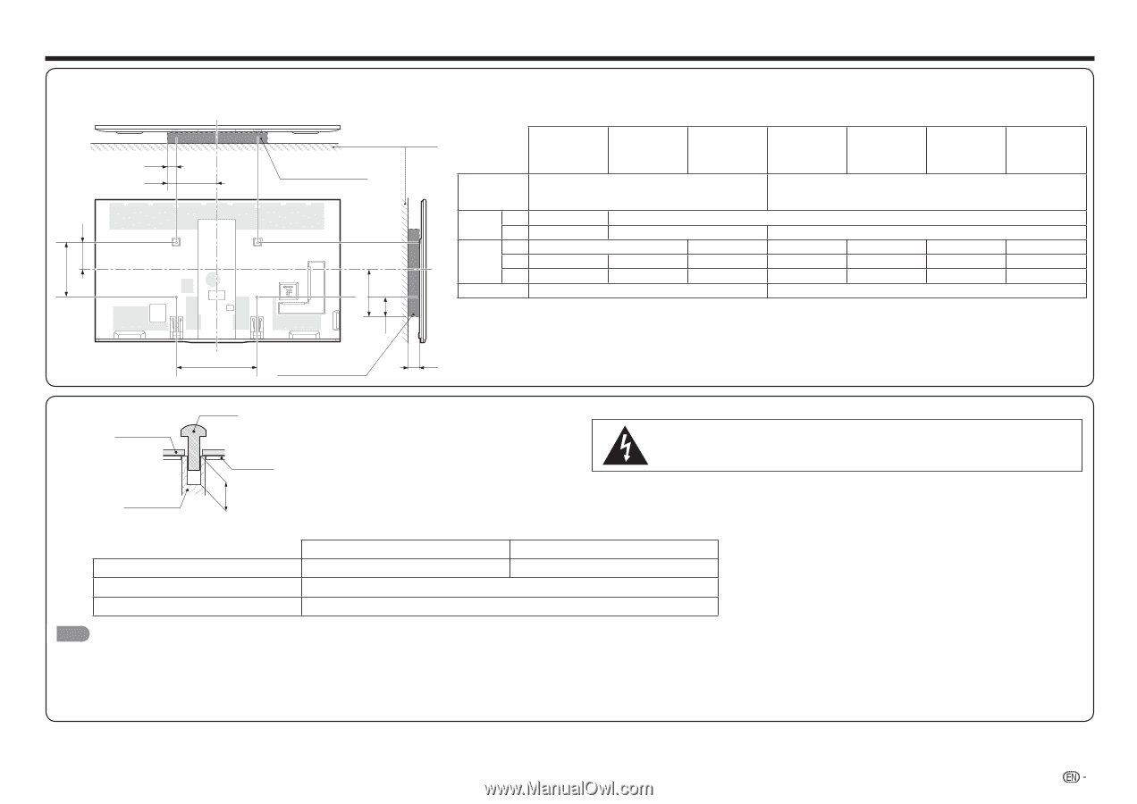
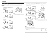
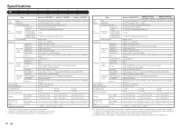
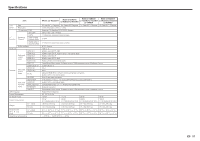
Appendix Wall Mount Kit Specifications Standard dimensions for wall mount kits are shown below. • The illustration is based on the LC-80LE857U model as an example. a1 a2 WALL MOUNT KIT B b1 b2 b3 A WALL MOUNT KIT WALL c1 LC-90LE657U LC-80LE857U/ LC-80LE757U LC-80LE657U/ LC-80LE650U/ LC-80C6500U VESA screw hole specs (A-B) a1 Width a2 b1 Height b2 b3 c1 23 5/8 (600) - 15 3/4 (400) 1 37/64 (40) 13 25/64 (340) 7 7/8 (200) 14 49/64 (375) 6 57/64 (175) 3 5/32 (80) 2 61/64 (75) 14 49/64 (375) 13 19/32 (345) 5 23/32 (145) 10 41/64 (270) 11 1/32 (280) 5 59/64 (150) a1: Maximum distance from the mounting hole a2: Maximum distance from the TV's center b1: Distance between the TV's center and the mounting hole b2: Maximum distance from the TV's center b3: Maximum distance from the mounting hole c1: Minimum gap LC-70LE857U/ LC-70LE757U/ LC-70LE755U/ LC-70C7500U LC-70LE657U/ LC-70LE655U/ LC-70LE650U/ LC-70C6500U 15 3/4 (400) - 15 3/4 (400) 10 27/32 (275) 7 7/8 (200) 14 11/64 (360) 6 5/16 (160) 2 49/64 (70) 7 31/64 (190) 10 41/64 (270) 2 3/8 (60) LC-60LE857U/ LC-60LE757U/ LC-60LE755U/ LC-60C7500U 7 7/8 (200) 12 39/64 (320) 4 47/64 (120) LC-60LE657U/ LC-60LE655U/ LC-60LE650U/ LC-60C6500U 9 1/16 (230) 9 1/16 (230) 2 3/8 (60) WALL MOUNT UNIT SCREW CABINET Do not install the wall mount kit while your TV is turned on. It may result in personal injury due to electric shock. MOUNTING HOLES DEPTH OF MOUNTING HOLES For the screws, refer to the table shown below. Standard screws Length(Depth of mounting holes) Quantity 90/80 inch models M8 (Use 1.25 pitch screws.) 15/32 (12) 4 pcs. 70/60 inch models M6 (Use 1.0 pitch screws.) NOTE • Do not mount the TV at a tilt. • To use this TV mounted on a wall, remove the cable tie as needed. • Do not use screws that do not comply with the VESA standard screw specifications. • Do not use screws that are longer than the standard length. Screws that are too long may cause damage to the inside of the TV. • Do not fasten the screws too firmly or loosely. This may damage the product or cause the product to fall, leading to personal injury. SHARP is not liable for these kinds of accidents. • SHARP is not liable for product damage or personal injury when a non-VESA or non-specified wall mount is used or the consumer fails to follow the product installation instructions. 53
-
 1
1 -
2
-
3
-
4
-
5
-
6
-
7
-
8
-
9
-
10
-
11
-
12
-
13
-
14
-
15
-
16
-
17
-
18
-
19
-
20
-
21
-
22
-
23
-
24
-
25
-
26
-
27
-
28
-
29
-
30
-
31
-
32
-
33
-
34
-
35
-
36
-
37
-
38
-
39
-
40
-
41
-
42
-
43
-
44
-
45
-
46
-
47
-
48
-
49
-
 50
50 -
 51
51 -
 52
52 -
 53
53 -
 54
54 -
 55
55 -
 56
56 -
 57
57 -
 58
58 -
 59
59 -
 60
60 -
61
-
62
-
63
-
64
-
65
-
66
 |
 |