Sharp LC-C4655U Service Manual - Page 32
Component 33K signal adjustment, 6. Analog RGB signal adjustment, 7. Tuner/V-Chip test
 |
UPC - 074000371569
View all Sharp LC-C4655U manuals
Add to My Manuals
Save this manual to your list of manuals |
Page 32 highlights
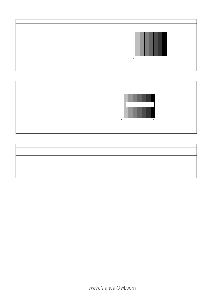
LC-C4655U 7.5. Component 33K signal adjustment Adjustment item 1 Adjustment Adjustment conditions Adjustment procedure 1080i signal Feed the 100% color bar signal to INPUT 1 component input. 2 Auto adjustment performance Page 6/38 7.6. Analog RGB signal adjustment 100% white Bring the cursor on [•COMP 33K ADJ (INPUT1)] and press [ENTER]. [•COMP 33K ADJ (INPUT1) OK] appears when finished. Adjustment item 1 Adjustment Adjustment conditions Analog RGB signal: XGA (1024 x 768) 60Hz SYNC: HV separate Adjustment procedure Feed the XGA 100% color bar signal to ANALOG RGB input. 100% Color saturation XGA 100% color bar 2 Auto adjustment performance 7.7. Tuner/V-Chip test Adjustment item 1 Adjustment 2 Auto adjustment performance 100% white 0% black Bring the cursor on [•ANALOG RGB ADJ] and press [ENTER]. [•ANALOG RGB ADJ OK] appears when finished. Adjustment conditions NTSC RF signal US-7 (AIR) ch Adjustment procedure Feed the NTSC signal to RF ANTENNA input. Bring the cursor on [•TUNER VCHIP TEST (*07ch)] and press [ENTER]. (*Select the channel according to the RF signal.) [•A-OK (***.**)/VM-OK] appears in blue when finished. (If [A-NG/VMNG] appears in yellow or red, the test is incomplete.) Make sure a displacement of ±0.0625 MHz from the center frequency is acceptable. 5 - 13
-
 1
1 -
2
-
3
-
4
-
5
-
6
-
7
-
8
-
9
-
10
-
11
-
12
-
13
-
14
-
15
-
16
-
17
-
18
-
19
-
20
-
21
-
22
-
23
-
24
-
25
-
26
-
 27
27 -
 28
28 -
 29
29 -
 30
30 -
 31
31 -
 32
32 -
 33
33 -
 34
34 -
 35
35 -
 36
36 -
 37
37 -
38
-
39
-
40
-
41
-
42
-
43
-
44
-
45
-
46
-
47
-
48
 |
 |