Sharp LC32SB27U Service Manual - Page 17
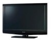
Control Button Ass'y, Control Button, LED Unit, Speaker-L, Speaker-R, KEY Unit, Front Cabinet Ass'y
 |
UPC - 074000372115
View all Sharp LC32SB27U manuals
Add to My Manuals
Save this manual to your list of manuals |
Page 17 highlights
LC-32D47U/LC-32SB27U/LC-C3237U 2. Removing of Speaker L/R, Control Button Ass'y, Front Cabinet Ass'y, LED Unit and KEY Unit. 1. Disconnect the following connectors from the Main Unit. (RA, SP) 2. Detach the Speaker-L 1 and Speaker-R 2 . 3. Detach the LED Unit 3 . 4. Disconnect the following connector from the LED Unit. (RA) 5. Remove the Control Button Ass'y. 6. Detach the KEY Unit 5 from the Control Button 4 and disconnect the connection cord from the KM connector. 7. Remove the 4 lock screws 6 , 6 hooks 7 and detach the Front Cabinet Ass'y. 6 7 7 Front Cabinet Ass'y KEY Unit 5 Control Button 4 [KM] [RA] [SP] Control Button Ass'y 7 7 7 7 LED Unit 3 [RA] 6 [SP] 2 Speaker-R Speaker-L 1 4 - 2
-
 1
1 -
2
-
3
-
4
-
5
-
6
-
7
-
8
-
9
-
10
-
11
-
 12
12 -
 13
13 -
 14
14 -
 15
15 -
 16
16 -
 17
17 -
 18
18 -
 19
19 -
 20
20 -
 21
21 -
 22
22 -
23
-
24
-
25
-
26
-
27
-
28
-
29
-
30
-
31
-
32
-
33
-
34
-
35
-
36
-
37
-
38
-
39
-
40
-
41
-
42
-
43
-
44
-
45
-
46
-
47
-
48
-
49
-
50
-
51
-
52
-
53
-
54
-
55
-
56
-
57
-
58
-
59
-
60
-
61
-
62
-
63
-
64
-
65
-
66
-
67
-
68
-
69
-
70
-
71
-
72
-
73
-
74
-
75
-
76
-
77
-
78
-
79
-
80
-
81
-
82
-
83
-
84
-
85
-
86
-
87
-
88
-
89
-
90
-
91
-
92
-
93
-
94
-
95
-
96
-
97
-
98
-
99
-
100
-
101
-
102
-
103
-
104
-
105
-
106
-
107
-
108
-
109
-
110
-
111
-
112
-
113
-
114
-
115
-
116
-
117
-
118
-
119
-
120
-
121
-
122
-
123
-
124
-
125
-
126
-
127
-
128
 |
 |

LC-32D47U/LC-32SB27U/LC-C3237U
4 – 2
2. Removing of Speaker L/R, Control Button Ass’y, Front Cabinet Ass’y, LED Unit and KEY Unit.
1.
Disconnect the following connectors from the Main Unit. (RA, SP)
2.
Detach the Speaker-L
and Speaker-R
3.
Detach the LED Unit
4.
Disconnect the following connector from the LED Unit. (RA)
5.
Remove the Control Button Ass’y.
6.
Detach the KEY Unit
from the Control Button
and disconnect the connection cord from the KM connector.
7.
Remove the 4 lock screws
, 6 hooks
and detach the Front Cabinet Ass’y.
1
2
3
5
4
6
7
6
7
7
Control Button Ass'y
4
Control Button
3
LED Unit
1
7
7
2
Speaker-L
Speaker-R
5
KEY Unit
Front Cabinet Ass'y
6
7
7
[SP]
[RA] [SP]
[KM]
[RA]