Sharp LC32SB27U Service Manual - Page 43
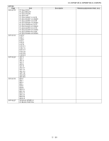
Tuner/V-Chip test
 |
UPC - 074000372115
View all Sharp LC32SB27U manuals
Add to My Manuals
Save this manual to your list of manuals |
Page 43 highlights
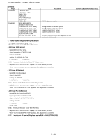
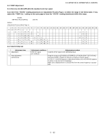
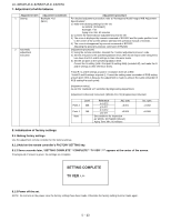
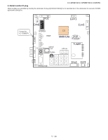
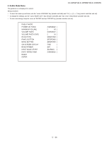
6.2. TEMP Adjustment LC-32D47U/LC-32SB27U/LC-C3237U 6.2.1 Receive US-10ch(JPN-8ch) the standard color bar signal 6.2.2 See if the "YDATA" reading (maximum) on Adjustment Process Page 1 is within the range in the follow table. If not, adjust the "TEMP ALL" setting on the same page to have the "YDATA" reading (maximum) within this range. MODEL SETTING VALUE (NTSC) 163-170 Refines (Adjustment Process Menu Page 1) 0 1 2 3 4 5 6 7 8 9 10 11 12 13 14 15 16 17 18 19 20 21 22 23 24 25 26 0 DVP 1 1 T AMP 1 L 163 2 YDATA 98 3 T AMP 1 H 170 4 T AMP ALL OF F 5 NTSC T AMP 1 77 6 PAL -M T AMP 64 7 PAL -N T AMP 64 6.3. Tuner/V-Chip test Adjustment item 1 Adjustment 2 Auto adjustment performance Adjustment conditions NTSC RF signal US-7 (AIR) ch Adjustment procedure Feed the NTSC signal to RF ANTENNA input. Bring the cursor on [OTHERS]→[OTERRS2]→[.TUNER VCHIP TEST (*07ch)] and press [LEFT]. (*Select the channel according to the RF signal.) [.A-OK (***.**)/VM-OK] appears in blue when finished. (If [A-NG/VM-NG] appears in yellow or red, the test is incomplete.) Make sure a displacement of ±0.0625 MHz from the center frequency is acceptable. 5 - 22
-
 1
1 -
2
-
3
-
4
-
5
-
6
-
7
-
8
-
9
-
10
-
11
-
12
-
13
-
14
-
15
-
16
-
17
-
18
-
19
-
20
-
21
-
22
-
23
-
24
-
25
-
26
-
27
-
28
-
29
-
30
-
31
-
32
-
33
-
34
-
35
-
36
-
37
-
 38
38 -
 39
39 -
 40
40 -
 41
41 -
 42
42 -
 43
43 -
 44
44 -
 45
45 -
 46
46 -
 47
47 -
 48
48 -
49
-
50
-
51
-
52
-
53
-
54
-
55
-
56
-
57
-
58
-
59
-
60
-
61
-
62
-
63
-
64
-
65
-
66
-
67
-
68
-
69
-
70
-
71
-
72
-
73
-
74
-
75
-
76
-
77
-
78
-
79
-
80
-
81
-
82
-
83
-
84
-
85
-
86
-
87
-
88
-
89
-
90
-
91
-
92
-
93
-
94
-
95
-
96
-
97
-
98
-
99
-
100
-
101
-
102
-
103
-
104
-
105
-
106
-
107
-
108
-
109
-
110
-
111
-
112
-
113
-
114
-
115
-
116
-
117
-
118
-
119
-
120
-
121
-
122
-
123
-
124
-
125
-
126
-
127
-
128
 |
 |
