Sharp MX-C301W Installation Manual - Page 6
Late, 0late
 |
View all Sharp MX-C301W manuals
Add to My Manuals
Save this manual to your list of manuals |
Page 6 highlights
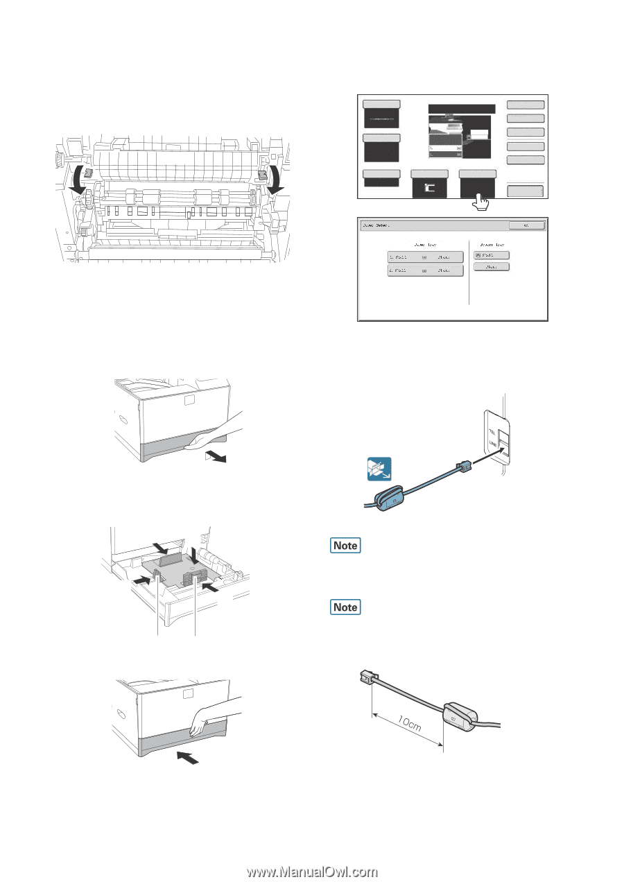
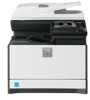
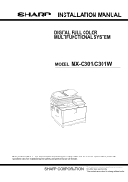
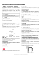
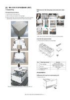
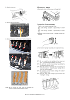
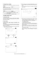
D. Fusing unit lever 1) Open the right door unit.. 2) Turn the levers of the Fusing unit to add the pressure. * Only the levers can add or release the pressure. There is no screw for adding or releasing the pressure. 4) Touch the [Paper Select] key. Then, select the tray that the customer wants to use by touching the key of the desired tray. NOTE: When the machine is left for one month without using, the Fusing heat roller could be deformed. If the machine is not going to be used for an extended period, release the pressure on the fusing rollers. E.Tray size setup 1) Gently pull out the tray until it stops. If paper is in the tray, remove it. F.Line cable connection (Only for the machine with FAX) 1) Connect the telephone line to the modular jack indicated as "LINE." 2) Adjust the guide plates A and B to the vertical size and the horizontal size of paper. The guide plates A and B are movable. Hold the fixing knob to slide the guide plates A and B to match the paper size. (2) (1) (2) (2) 3) Insert the tray slowly. It is necessary to prepare the line cable by yourself. The telephone cable does not come with the machine. When connecting the line cable (to LINE or TEL), wind the line cable two turns around the included ferrite core as shown in the figure, and connect to the modular jack which is marked with "LINE." MX-C301 MX-C301/C301W(MAIN UNIT) 2 - 3
-
 1
1 -
 2
2 -
 3
3 -
 4
4 -
 5
5 -
 6
6 -
 7
7
 |
 |