Sharp PN-E702 PN-E702 Professional LCD Monitor Operation Manual - Page 10
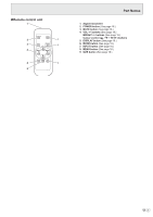
Part Names - remote control
 |
View all Sharp PN-E702 manuals
Add to My Manuals
Save this manual to your list of manuals |
Page 10 highlights
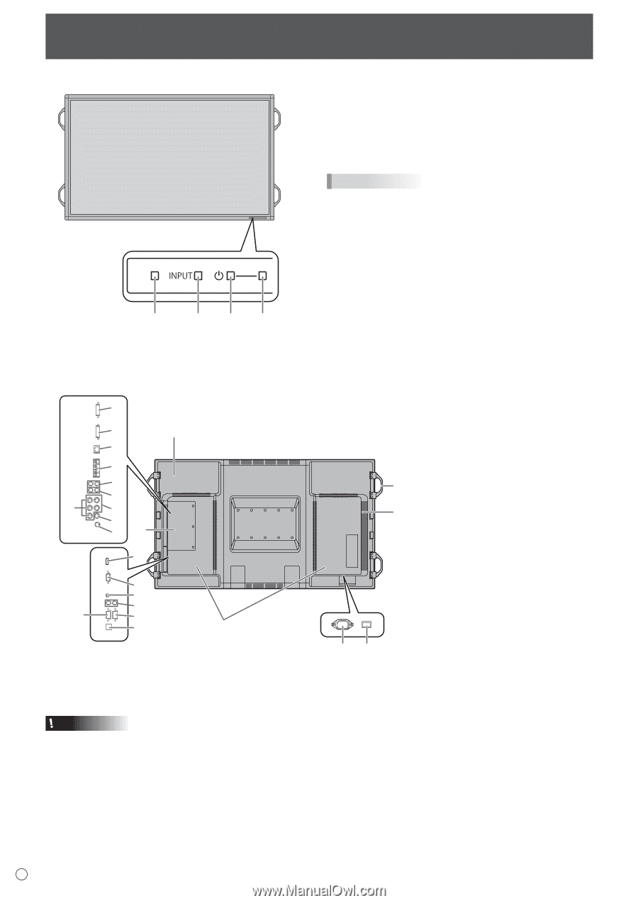
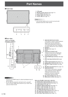
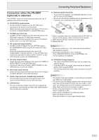
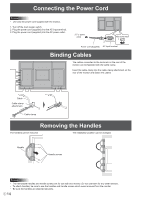
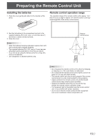
nFront view 1 Part Names 1. LCD panel 2. Remote control sensor (See page 15.) 3. Input switch (See page 18.) 4. Power switch (See page 16.) 5. Power LED (See page 16.) TIPS • Use a pointed object such as a pen tip to press the switches at the front of the monitor. 2 3 4 5 nRear view When the PN-ZB01 (optional) is attached 15 16 1 17 18 19 20 22 21 23 24 5 6 7 8 9 11 10 12 2 Caution • Consult your SHARP dealer for attachment/detachment of optional parts. • Do not open the expansion terminal cover by yourself. There are high voltage parts inside the cover which may cause an electric shock. E 10 13 14 1. Optional attachment section This section is used to connect optional hardware for function expansion. Offering this attachment location is not a guarantee that future compatible hardware attachments will be released. 2. Speakers 3. Handles (See page 14.) 4. Vents 5. Expansion terminal cover 3 Additional input/output terminals are available by attaching the PN-ZB01 4 expansion board (optional). 6. PC/AV HDMI input terminal (See page 12.) 7. PC D-sub input terminal (See page 12.) 8. Audio input terminal (See page 12.) 9. Audio output terminals (See page 12.) 10. RS-232C output terminal (See page 12.) 11. RS-232C input terminal (See page 12.) 12. Optional terminal This terminal is provided for possible future (optional) function expansion. Offering of this terminal is not a guarantee that future expanded functionality will be provided. 13. AC input terminal (See page 14.) 14. Main power switch (See page 16.) When the PN-ZB01 (optional) is attached 15. PC/AV DVI-D input terminal (See page 13.) 16. PC/AV DVI-D output terminal (See page 13.) 17. LAN terminal (See page 13.) 18. External speaker terminals (See page 13.) 19. Audio 1 input terminals (See page 13.) 20. Audio 2 input terminals (See page 13.) 21. PC RGB input terminals (See page 13.) 22. AV component input terminals (See page 13.) 23. AV video input terminal (See page 13.) 24. AV S-video input terminal (See page 13.)
-
 1
1 -
2
-
3
-
4
-
 5
5 -
 6
6 -
 7
7 -
 8
8 -
 9
9 -
 10
10 -
 11
11 -
 12
12 -
 13
13 -
 14
14 -
 15
15 -
16
-
17
-
18
-
19
-
20
-
21
-
22
-
23
-
24
-
25
-
26
-
27
-
28
-
29
-
30
-
31
-
32
-
33
-
34
-
35
-
36
-
37
-
38
-
39
-
40
-
41
-
42
-
43
-
44
-
45
-
46
-
47
-
48
-
49
-
50
-
51
-
52
-
53
-
54
-
55
-
56
-
57
 |
 |