Sharp R-1505F Service Manual - Page 18
Blown Monitor Fuse Test, Hood Thermal Cut-out Test, Hood Fan Motor Test, Lock Relay
 |
View all Sharp R-1505F manuals
Add to My Manuals
Save this manual to your list of manuals |
Page 18 highlights
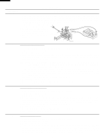
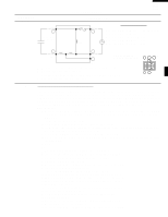
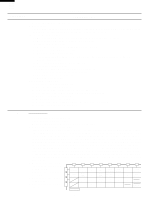
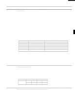
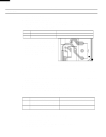
R-1500 R-1501 R-1505 R-1506 TEST PROCEDURES PROCEDURE LETTER COMPONENT TEST plate of the oven cavity with the door opened (in this condition the plunger of the monitor switch is pushed in), the meter should indicate an open circuit. If improper operation is indicated, the switch may be defective. After testing the monitor switch, reconnect the wire lead to the monitor switch (COM) terminal and check the continuity of the monitor circuit. 5. Reconnect all leads removed from components during testing. 6. Reinstall the outer case (cabinet). Red White/ White 7. Reconnect the power supply cord after the outer case is installed. Screw Driver 8. Run the oven and check all functions. Ohmmeter Primary Interlock Switch Monitor Switch I BLOWN MONITOR FUSE TEST 1. Disconnect the power supply cord, and then remove outer case. 2. Open the door and block it open. 3. Discharge high voltage capacitor. 4. If the monitor fuse is blown when the door is opened, check the secondary interlock relay, primary interlock switch and monitor switch according to the "TEST PROCEDURE" for those switches before replacing the blown monitor fuse. CAUTION: BEFORE REPLACING A BLOWN MONITOR FUSE, TEST THE SECONDARY INTERLOCK RELAY, PRIMARY INTERLOCK SWITCH, DOOR SENSING SWITCH AND MONITOR SWITCH FOR PROPER OPERATION. If the monitor fuse is blown by improper switch operation, the monitor fuse and monitor switch must be replaced with "monitor fuse and monitor switch assembly" part number FFS-BA016/KiT, even if the monitor switch operates normally. The monitor fuse and monitor switch assembly is comprised of a 20 ampere fuse and switch. 5. Reconnect all leads removed from components during testing. 6. Re-install the outer case (cabinet). 7. Reconnect the power supply cord after the outer case is installed. 8. Run the oven and check all functions. J HOOD THERMAL CUT-OUT TEST 1. Disconnect the power supply cord, and then remove outer case. 2. Open the door and block it open. 3. Discharge high voltage capacitor. 4. A continuity check across the thermal cut-out terminals should indicate an open circuit unless the temperature of the thermal cut-out reaches approximately 140˚F(60˚C) or more. At that temperature, the contacts will close. The thermal cut-out opens automatically at approximately 113˚F(45˚C). 5. Reconnect all leads removed from components during testing. 6. Reinstall the outer case (cabinet). 7. Reconnect the power supply cord after the outer case is installed. 8. Run the oven and check all functions. K HOOD FAN MOTOR TEST 1. Disconnect the power supply cord, and then remove outer case. 2. Open the door and block it open. 3. Discharge high voltage capacitor. 4. If the motor does not turn, touch the FAN HI / LO button once (set hood fan motor power "HIGH") and check voltage between pins "1" and "2" (Blue and Black wires) of the 6 pin connector. If 120 Volts appear and the hood capacitor is good, replace the hood fan assembly. If 120 Volts does not appear, check the motor circuit. The resistance values of motor terminals are as follows: 16
-
 1
1 -
2
-
3
-
4
-
5
-
6
-
7
-
8
-
9
-
10
-
11
-
12
-
 13
13 -
 14
14 -
 15
15 -
 16
16 -
 17
17 -
 18
18 -
 19
19 -
 20
20 -
 21
21 -
 22
22 -
 23
23 -
24
-
25
-
26
-
27
-
28
-
29
-
30
-
31
-
32
-
33
-
34
-
35
-
36
-
37
-
38
-
39
-
40
-
41
-
42
-
43
-
44
 |
 |
