Sharp R-520JK KB-5121KS , KB-5121KK , KB-5121KW Installation Instructions - Page 7
Power Connections
 |
View all Sharp R-520JK manuals
Add to My Manuals
Save this manual to your list of manuals |
Page 7 highlights
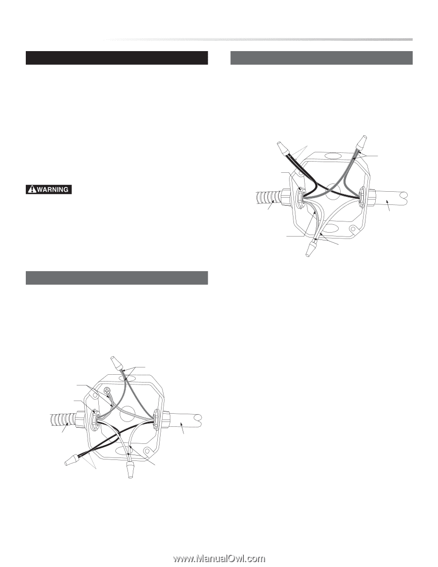
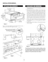
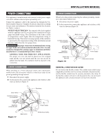
POWER CONNECTIONS This appliance is manufactured with a neutral (white) power supply wire and a cabinet-connected green grounding wire. Connect the appliance cable to the junction box through the ULlisted conduit connector. Complete electrical connection according to local codes and ordinances. For preferred junction box location, see Figure 2, page 2. NOTE TO ELECTRICIAN: The armored cable leads supplied with this appliance are UL recognized for connection to larger gauge household wiring. The installation of the leads is rated at temperatures much higher than the temperature rating of household wiring. The current carrying capacity of the conductor is governed by the temperature rating of the installation around the wire, rather than the wire gauge alone. Improper connection of aluminum house wiring to copper leads can result in an electrical hazard or fire. Use only connectors designed for joining copper to aluminum and follow manufacturer's recommended procedure closely. GENERAL NOTE FOR WIRE NUT APPLICATIONS: The proper size wire nut shall be placed over the stripped leads and the wire nut twisted until the wire nut can not be pulled from the leads. No conductor shall be exposed in the connection. 4-WIRE CONNECTION When installing to a 4-wire electrical system, new construction, mobile home and recreational vehicle or when local codes do not permit grounding through neutral. 1 Disconnect the power supply. 2 In the junction box connect the appliance and residence cable wires as shown in Figure 17. INSTALLATION MANUAL 3-WIRE CONNECTION When local codes permit connecting the cabinet-grounding conductor to the neutral (white) wire. 1 Disconnect the power supply. 2 In the junction box connect the appliance and residence cable wires as shown in Figure 18. Conduit connector (not supplied) Black wires Red wires Appliance conduit & wires Green wire (ground) Figure 18 Power supply White wires (nutral) REINSTALL JUNCTION BOX COVER Do not shorten the flexible conduit. The conduit strain relief clamp (supplied by installer) must be securely attached to the junction box and the flexible conduit must be securely attached to the clamp. If the flexible conduit will not fit with the junction box, do not install the appliance until a clamp of proper size has been obtained. Green wires Conduit connector (not supplied) Red wires Appliance conduit & wires Figure 17 Black wires Power supply White wires (nutral) 7
-
 1
1 -
 2
2 -
 3
3 -
 4
4 -
 5
5 -
 6
6 -
 7
7 -
 8
8
 |
 |